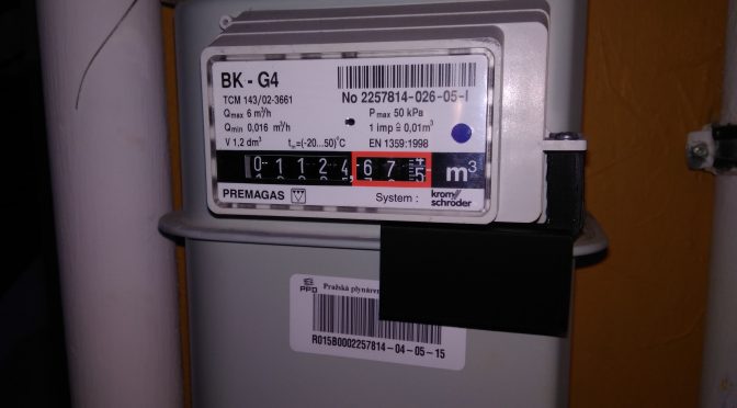
In my current flat the central heating runs on natural gas and I wanted to have a nice chart showing its consumption. The gas meter is directly in the hallway so everyone can see it. Because of this, I cannot simply bring in AC power and attach some exposed wires, otherwise my neighbors would probably call anti-terrorist group. The measuring device has to be small, look professional and have low power consumption so it can run on batteries. In next lines I’ll describe how I have achieved this.
Detecting pulses
First step was to discover how does the measurement work. I found out, one can buy original sensor attachable to my type of gas meter.

From the docs: “Operating principle: A pulse magnet in the first moving drum of the index type Z3/Z6 activates a reed switch in the pulse transmitter.” So you get pulses from reed switch (open circuit/closed circuit). Disassembled sensor can be seen on this page. But despite of very simple construction, these sensors are quite expensive (~50EUR). Fortunately (and thanks to Mr. Stehlik’s lecture), I’ve found a 3D printable sensor clip which only needs adding a reed switch for under 1EUR and you have a working sensor. So I printed one for test and it fitted perfectly.
Counting pulses
NodeMCU Amica
My first choice for making IoT device was esp8266 module, specifically NodeMCU Amica which I had at hand. I connected the output from reed switch to a data pin and wrote a simple application.
 Counting switch presses is easy, going into sleep was new to me but I managed to make it work. Power optimizations came to play then. I started to measure the power usage in sleep mode. My meter was showing 11mA at 4.5V which was way too high for battery powering. Then I tried to directly connect 3.3V voltage (behind regulator) and checked the current:
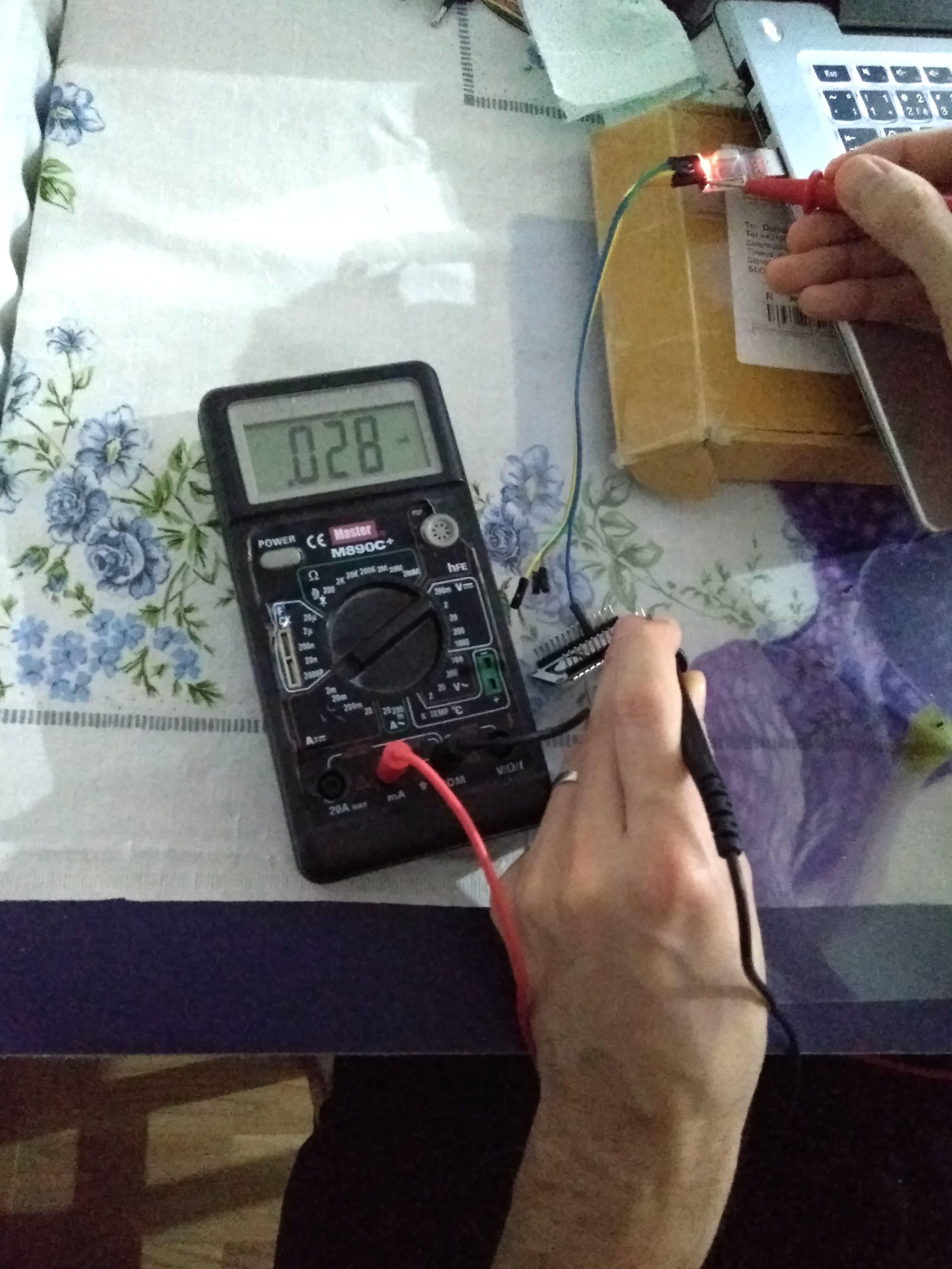 28uA was very nice result so I had to find the problem. I found out, that the USB-to-serial chip is powered from Vin so I tried to scrape it off:
 After this, the current dropped to 3mA but this was still too high. I checked the datasheet of onboard voltage regulator (AMS1117) and it needs 3mA solely for its operation so this board was out of game.
Wemos D1 mini
I checked some reviews on the Internet and found out that Wemos D1 mini boards should have better power regulator so I ordered one. When it came I did the measurement:
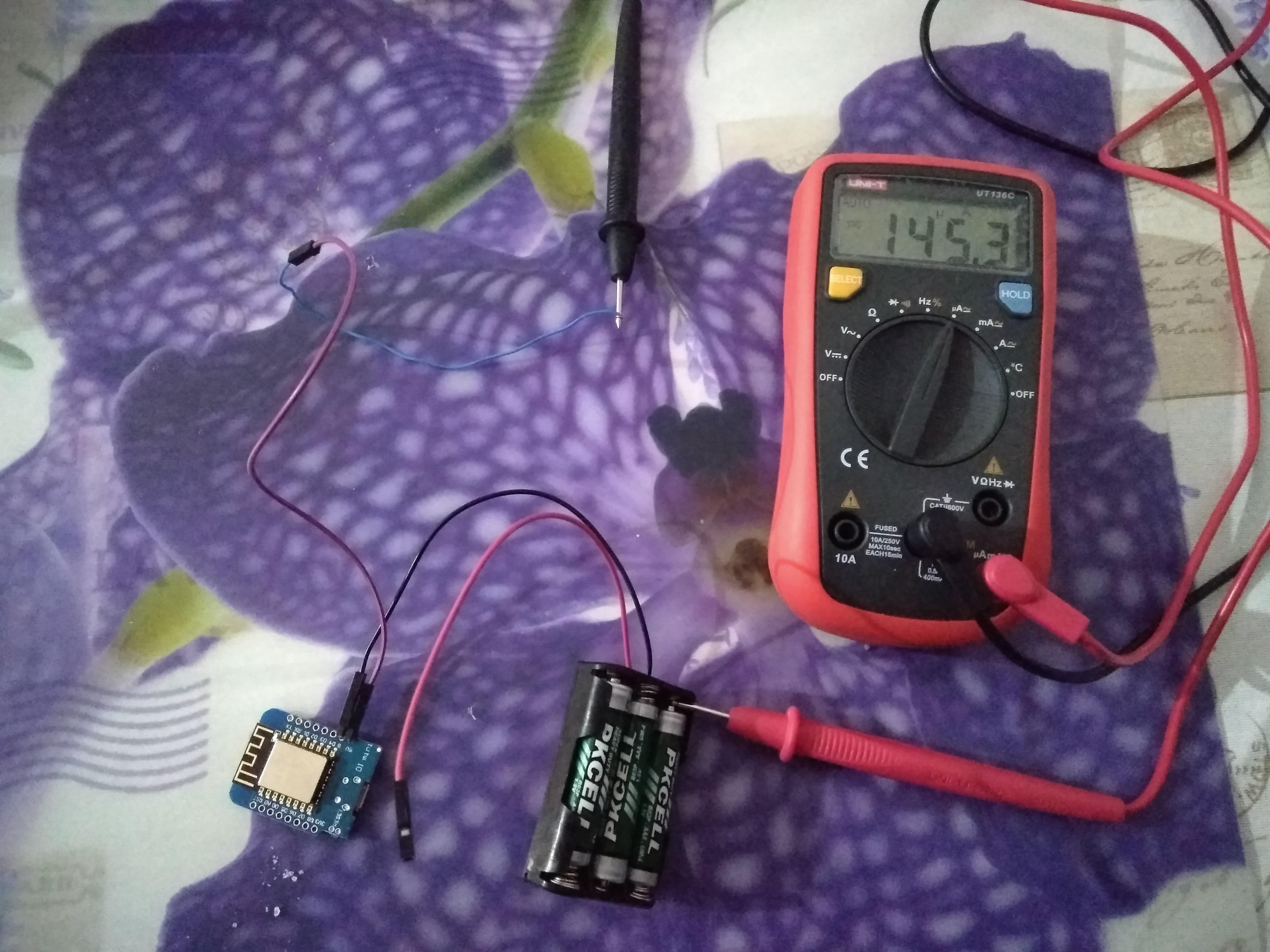 145.3uA is a decent result so I concentrated on consumption at count and transmit phase.
I did some tests and measurements and it takes hundreds of milliseconds to wakeup from sleep and to count the pulse and several seconds to connect and send the result via WiFi.
 I wasn’t satisfied with the result because I wanted it to last at least one year on batteries so I started to look for another solution.
AVR + 433MHz transmitter
Inspired by wireless thermometers I started to experiment with 433MHz transmitters and receivers. I though this could be a very low power solution so I ordered a pair of cheap TX, RX from ali. After some transfer tests I was not satisfied with the reception quality (see my RX test) and I also wanted to avoid interference and link level problems and their debugging so I moved to a higher level solution.
nRF51822
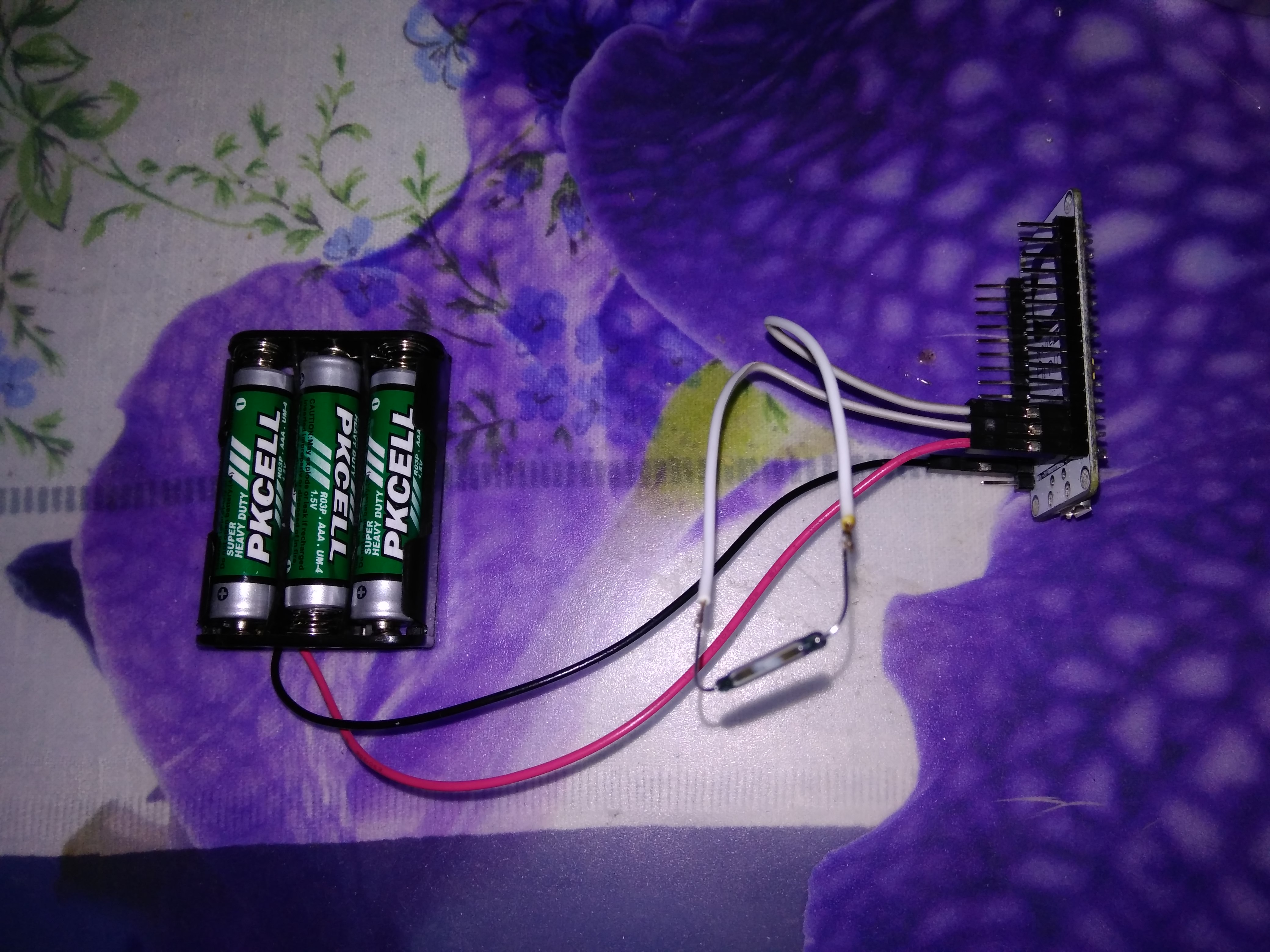
Bluetooth Low Energy (BLE, formerly Bluetooth Smart) is technology powering many smart devices (watches, beacons, fitness trackers, etc.) so it is perfectly optimized for low power consumption. My idea was to use a beacon mode to broadcast current gas counter value after each change and go back to sleep: without any connection establishment, authentication, back channel or standby mode. Just deep sleep, wait for interrupt from reed switch, shout new value, sleep again.
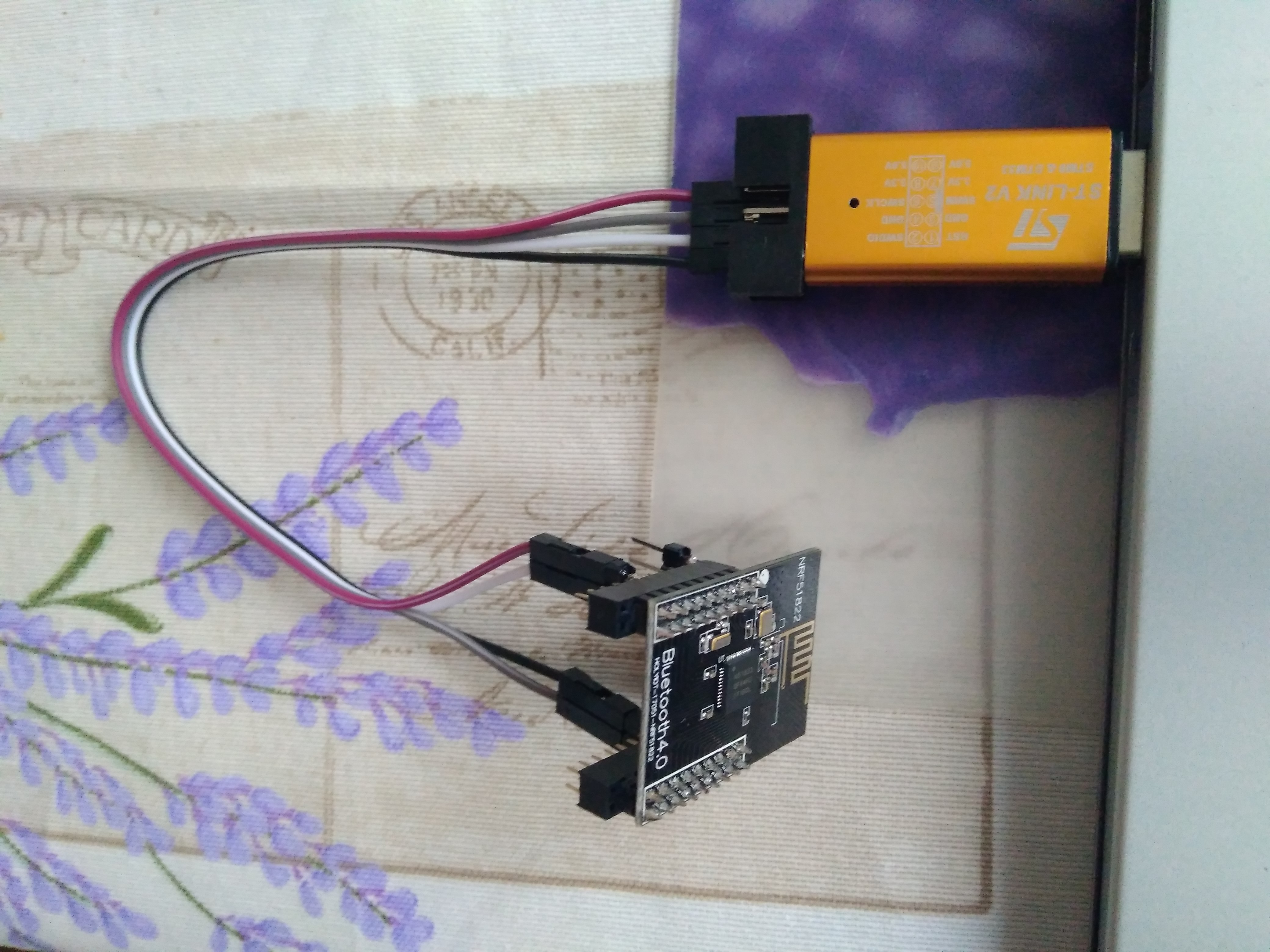
Aliexpress search showed one very cheap and compact BLE module so I gave it a try.
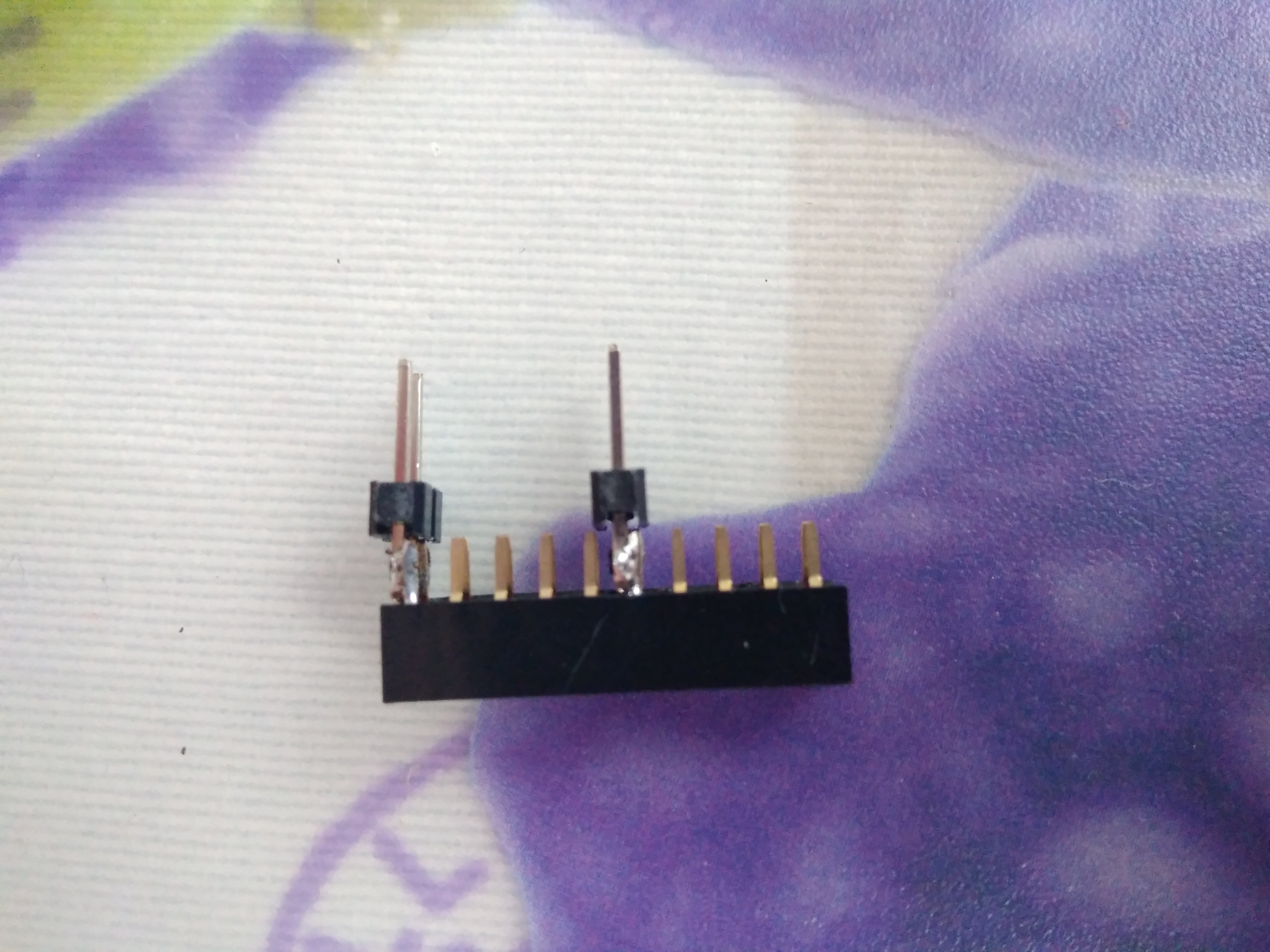
 The first surprise was that the pin pitch was not standard 2.54mm but 2mm. This was easily solved with correct pin header socket from local shop with soldered 2.54mm pin header.
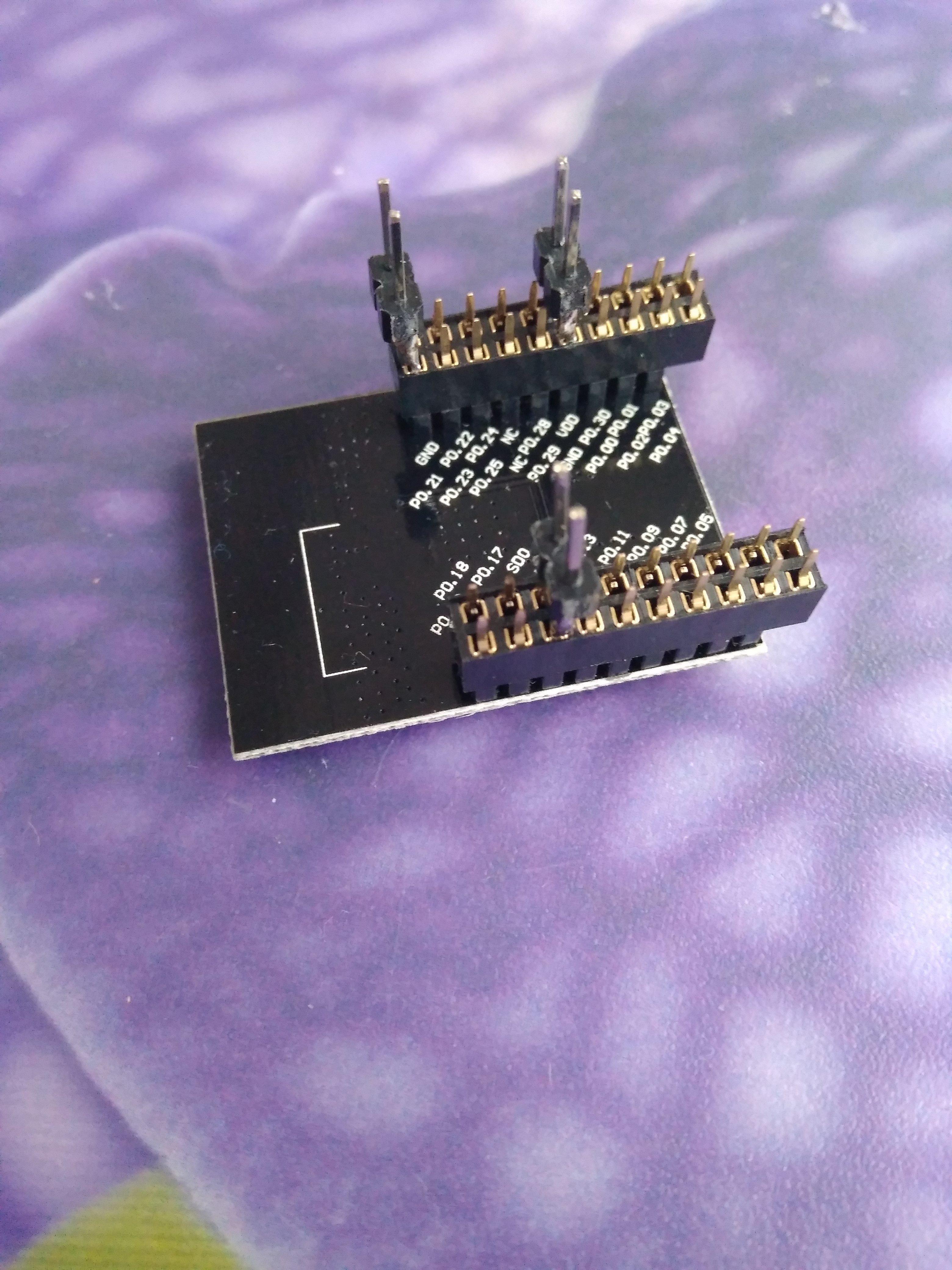
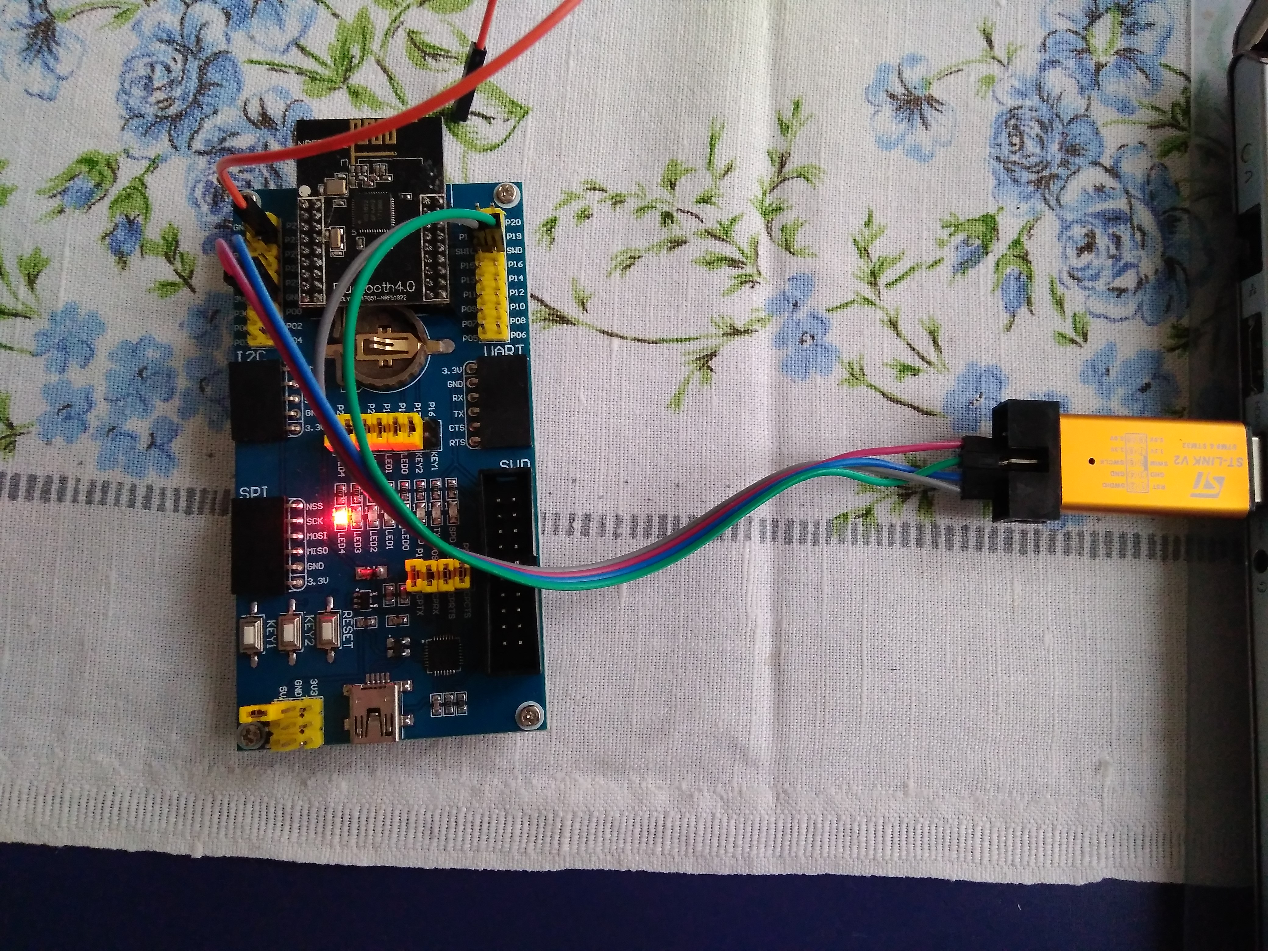
 Later on, I’ve ordered 2mm to 2.54mm jumper wires and then also this nice and handy expansion board.
Software
This was the hardest part of the whole project. I like to use PlatformIO (PIO) so I decided to use it again. It has support for nrf51 with both Arduino and Mbed frameworks. I found some example apps which compiled successfully. By default they use j-link adapter for upload so I needed to adopt them to use st-link by setting in platformio.ini:
upload_protocol = stlink
At that time it also required some changes to PIO but now it works out of the box. To use correct pin mapping with Arduino, I also had to set board to:
board = waveshare_ble400
Then I could develop some code but I stuck on configuring sleep mode and there is also very limited support for nrf51 in Arduino so I moved to Mbed.
It took me days to find working config for Mbed and I tried many many things. At the end I found out that setting following board was enough:
board = bbcmicrobit
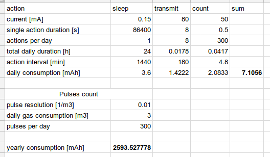
I quickly put together some code and tested the power consumption. The expected consumption in sleep was about 2.6uA according to this. The real one was following:
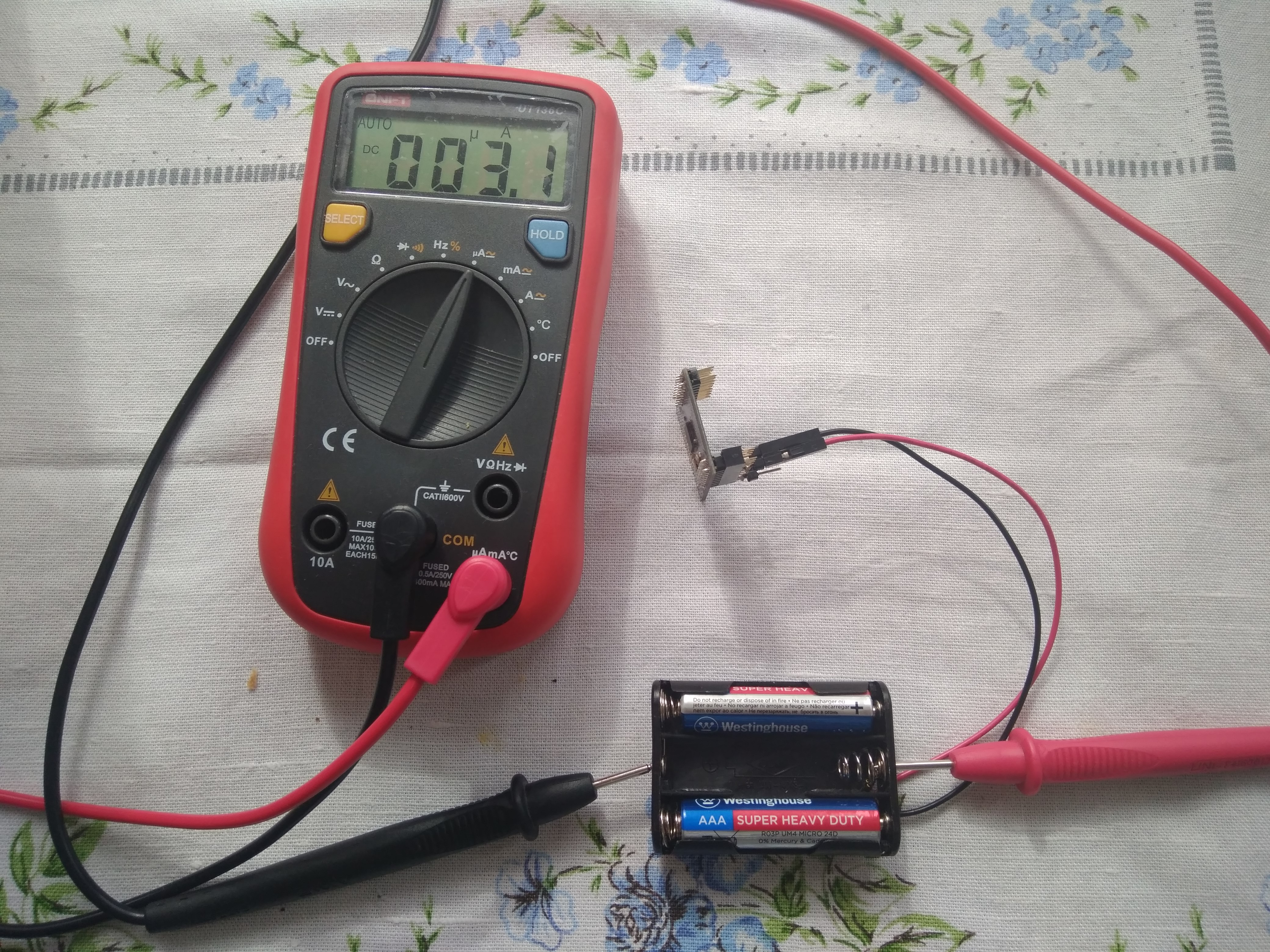
4.17mA when transmitting and 3.1µA in sleep so the power budget looks like this:
 When we take into account typical AAA battery capacity of about 540mAh it should theoretically last more than 3 years which is way better than I required (at least a year). Awesome!
Debouncing
Next I concentrated on correct pulse detection. I connected the reed switch to input pin with enabled pull-up. When I measured voltage on the reed switch it looked like this:  When the magnetic force switches the switch there is a short period of bouncing which could cause false pulse detection. This could be solved either by a RC circuit or by ignoring subsequent pulses for some time after detecting the first one in software. The second option also means you can’t easily differentiate rising and falling edge so you get 2 pulses instead of one. Nevertheless, I chose the second option because software is cheaper and easier to debug than an electrical circuit.
How does the software work
The principle of operation is simple: Normally it is in sleep. When it receives interrupt on pin with reed switch, it increases counter value and ignores subsequent pulses for certain time. The counter value is kept in RAM only to avoid flash wear. The software then configures BLE advertisement which contains JSON with current counter value and measured battery voltage.
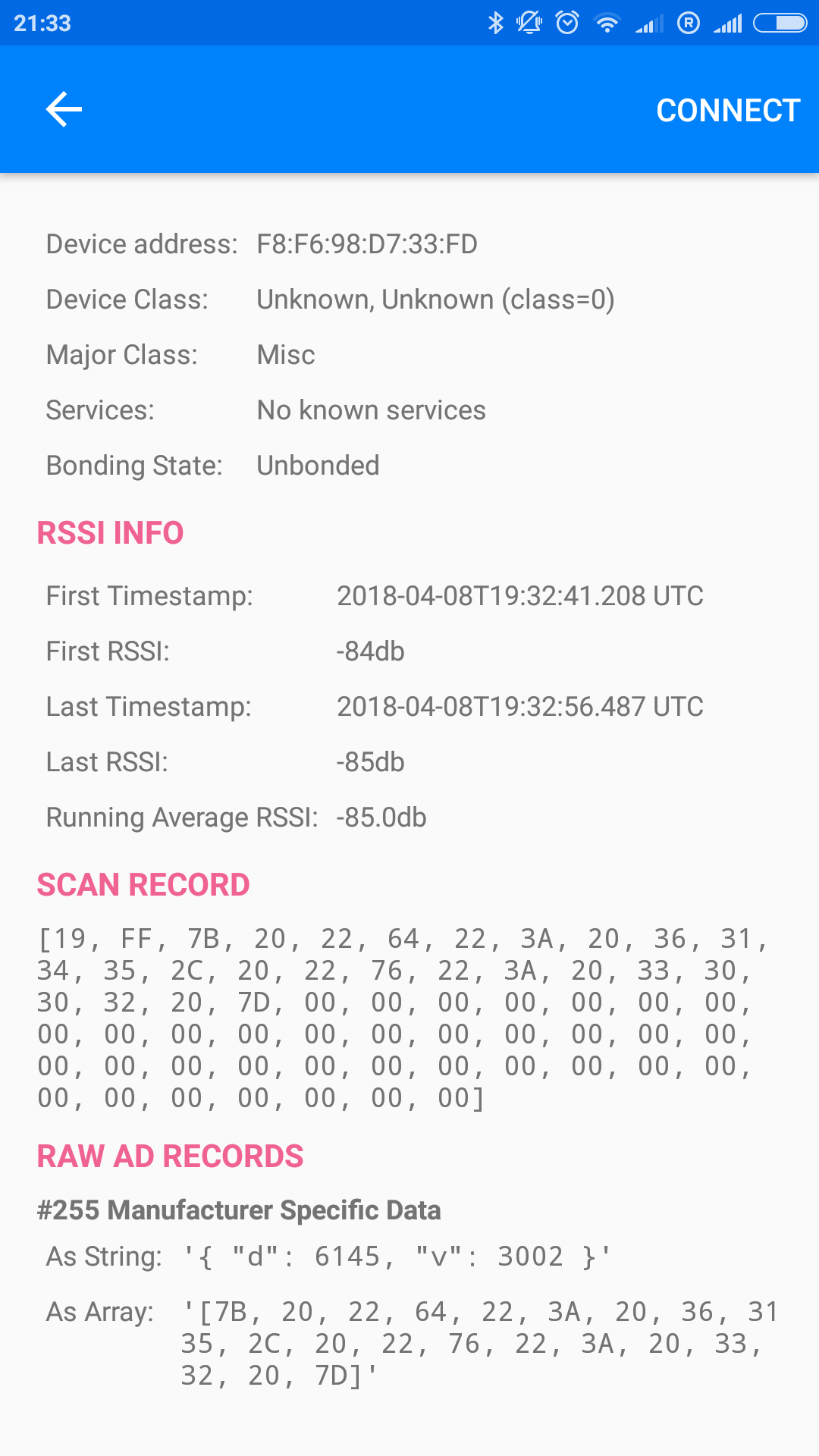 Then it starts sending this advertisement for 1 second and goes back into sleep and waits for next pulse. You can see the code here.
For debugging purposes, I run on my notebook on first shell:
$ sudo hcitool lescan --duplicates
LE Scan ...
F8:6A:94:76:A3:76 (unknown)
F8:6A:94:76:A3:76 (unknown)
F8:6A:94:76:A3:76 (unknown)
F8:6A:94:76:A3:76 (unknown)
F8:6A:94:76:A3:76 (unknown)
F8:6A:94:76:A3:76 (unknown)
F8:6A:94:76:A3:76 (unknown)
F8:6A:94:76:A3:76 (unknown)
F8:6A:94:76:A3:76 (unknown)
F8:6A:94:76:A3:76 (unknown)
F8:6A:94:76:A3:76 (unknown)
F8:6A:94:76:A3:76 (unknown)
F8:6A:94:76:A3:76 (unknown)
...
in another shell:
$ sudo hcidump --raw -w /dev/stdout | strings
btsnoop
{ "d": 79769, "v": 3111 }
{ "d": 79769, "v": 3111 }
{ "d": 79769, "v": 3111 }
{ "d": 79769, "v": 3111 }
{ "d": 79769, "v": 3111 }
{ "d": 79769, "v": 3111 }
{ "d": 79769, "v": 3111 }
{ "d": 79769, "v": 3111 }
{ "d": 79769, "v": 3111 }
{ "d": 79770, "v": 3111 }
{ "d": 79770, "v": 3111 }
{ "d": 79770, "v": 3111 }
{ "d": 79770, "v": 3111 }
{ "d": 79770, "v": 3111 }
{ "d": 79770, "v": 3111 }
{ "d": 79770, "v": 3111 }
{ "d": 79770, "v": 3111 }
{ "d": 79770, "v": 3111 }
{ "d": 79770, "v": 3111 }
{ "d": 79771, "v": 3111 }
{ "d": 79771, "v": 3111 }
{ "d": 79771, "v": 3111 }
{ "d": 79771, "v": 3111 }
{ "d": 79771, "v": 3111 }
{ "d": 79771, "v": 3111 }
{ "d": 79771, "v": 3111 }
{ "d": 79771, "v": 3111 }
{ "d": 79771, "v": 3111 }
To store the data I use Zabbix with MySQL. To get the data in, I connected USB bluetooth adapter with added antenna and wrote a simple data relay script in python:
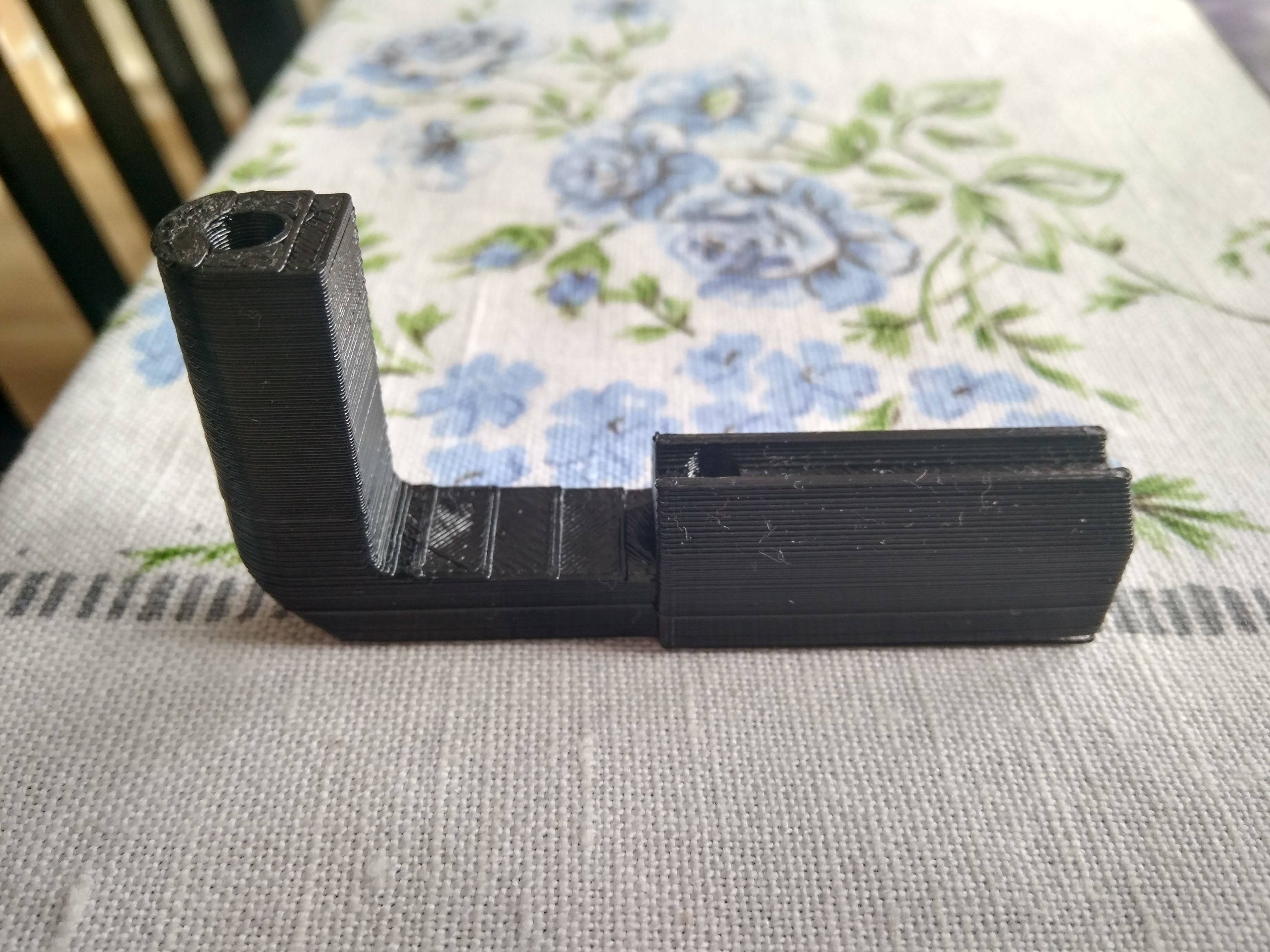
Case
When everything was working on a bench, I measured the dimensions and created a box derived from the original sensor clip. You can find my design on thingiverse.
Finally it looks like this:
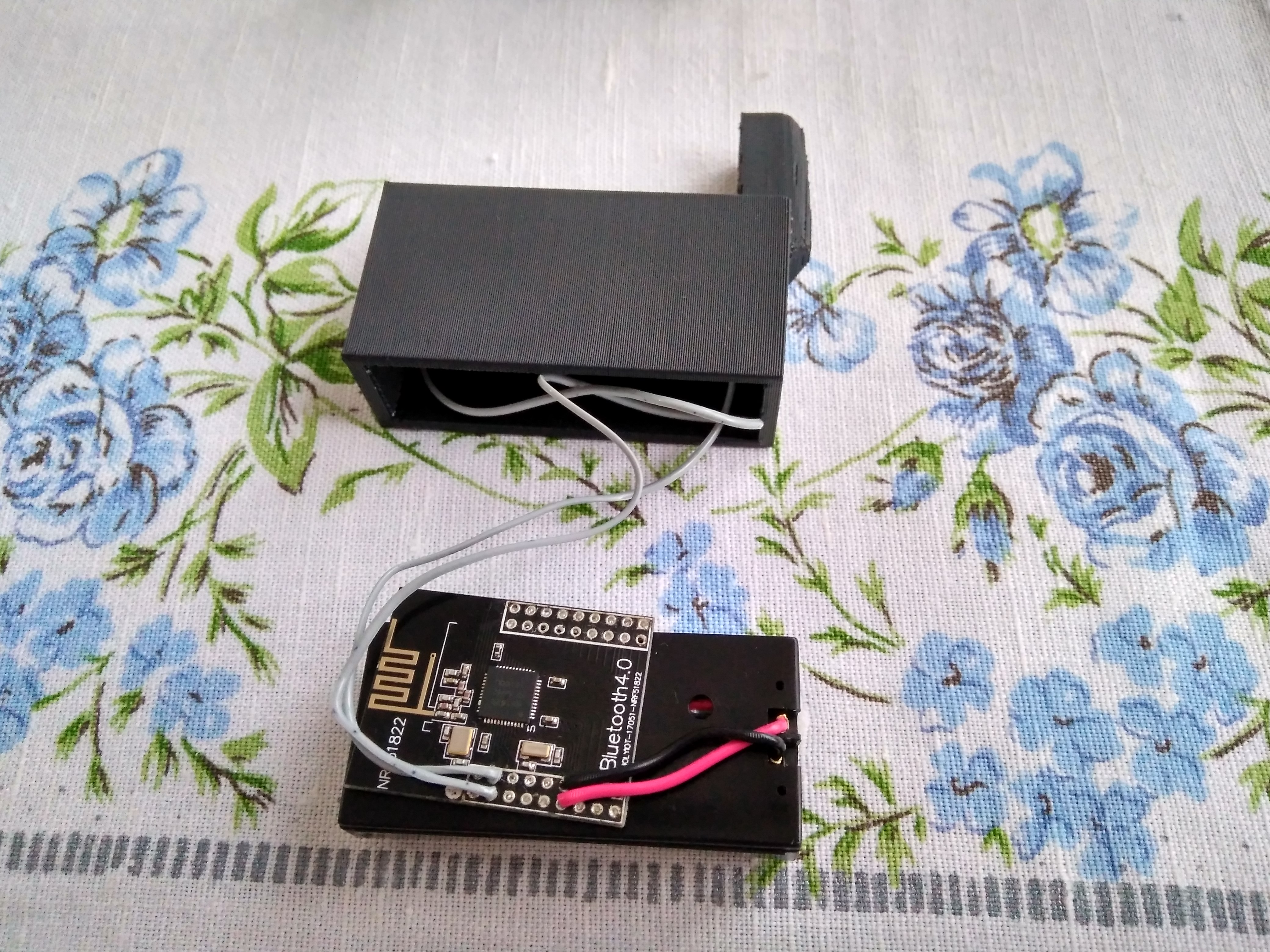
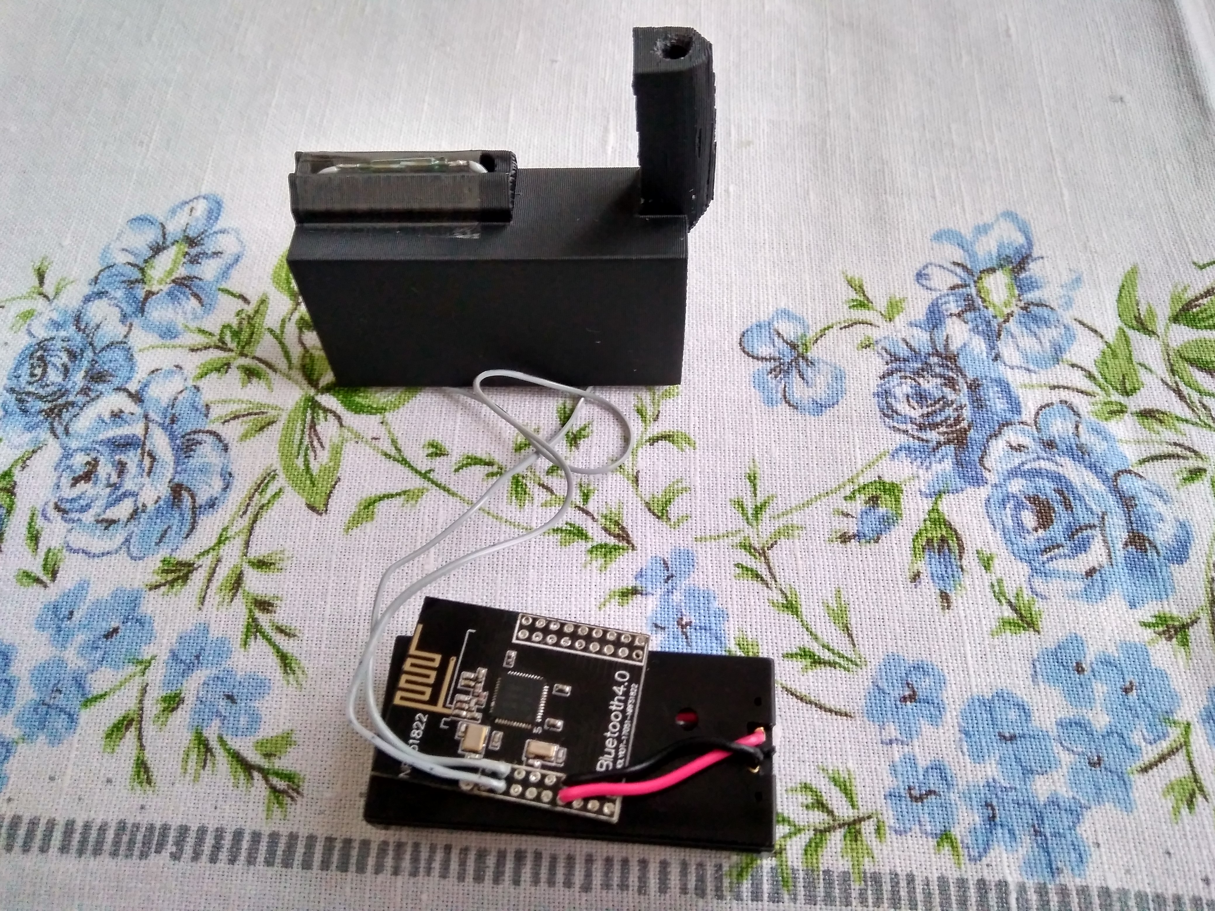

 I think it’s not bad for my first 3D design.
Performance
After a month in “production” I can share some data with you.
Battery voltage:
 With this discharge tempo it should last (3.16V – 1.8V) / ((3.16V – 2.98V)/30days) = cca 226 days BUT the discharge profile of cheapest zinc-carbon battery looks like this:
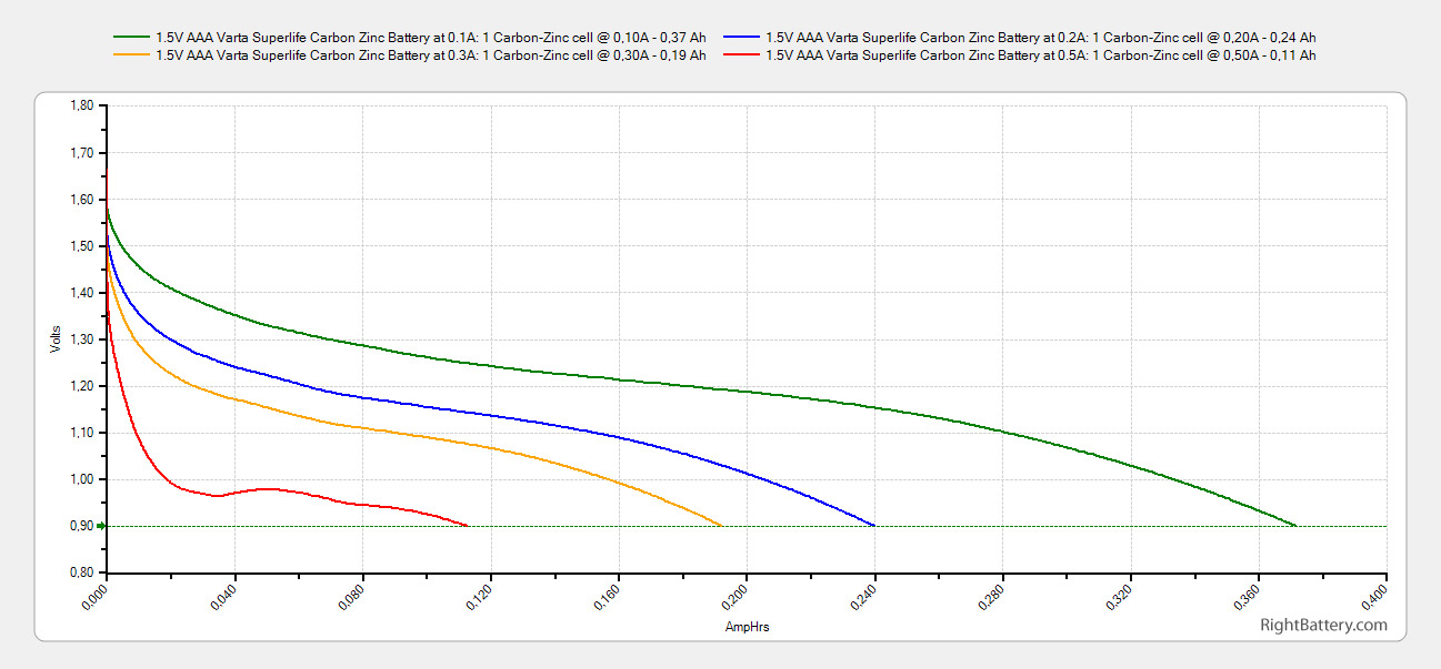
As you can see the discharge rate is highest in the beginning and then decreases and stabilizes so I guess it will last at least twice that long. I’ll post an update after some time, I’m lazy to make a proper extrapolation 😀 .
The data about gas consumption can be seen here:
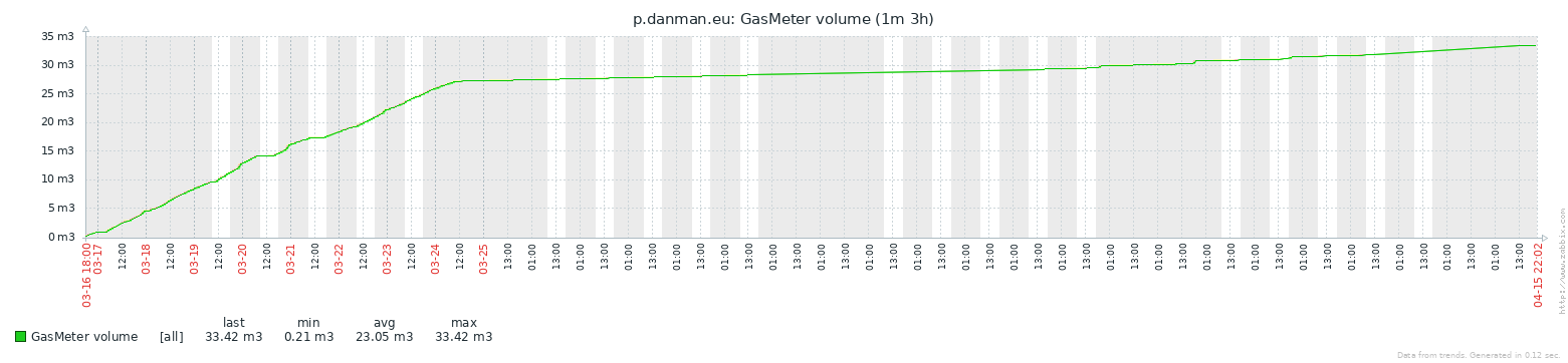 This view is OK for calculating consumption for some period but I want to see calculated daily consumption. Unfortunately, Zabbix can’t do this dynamically from stored data but Grafana can. And Grafana can use Zabbix data. So here it is:
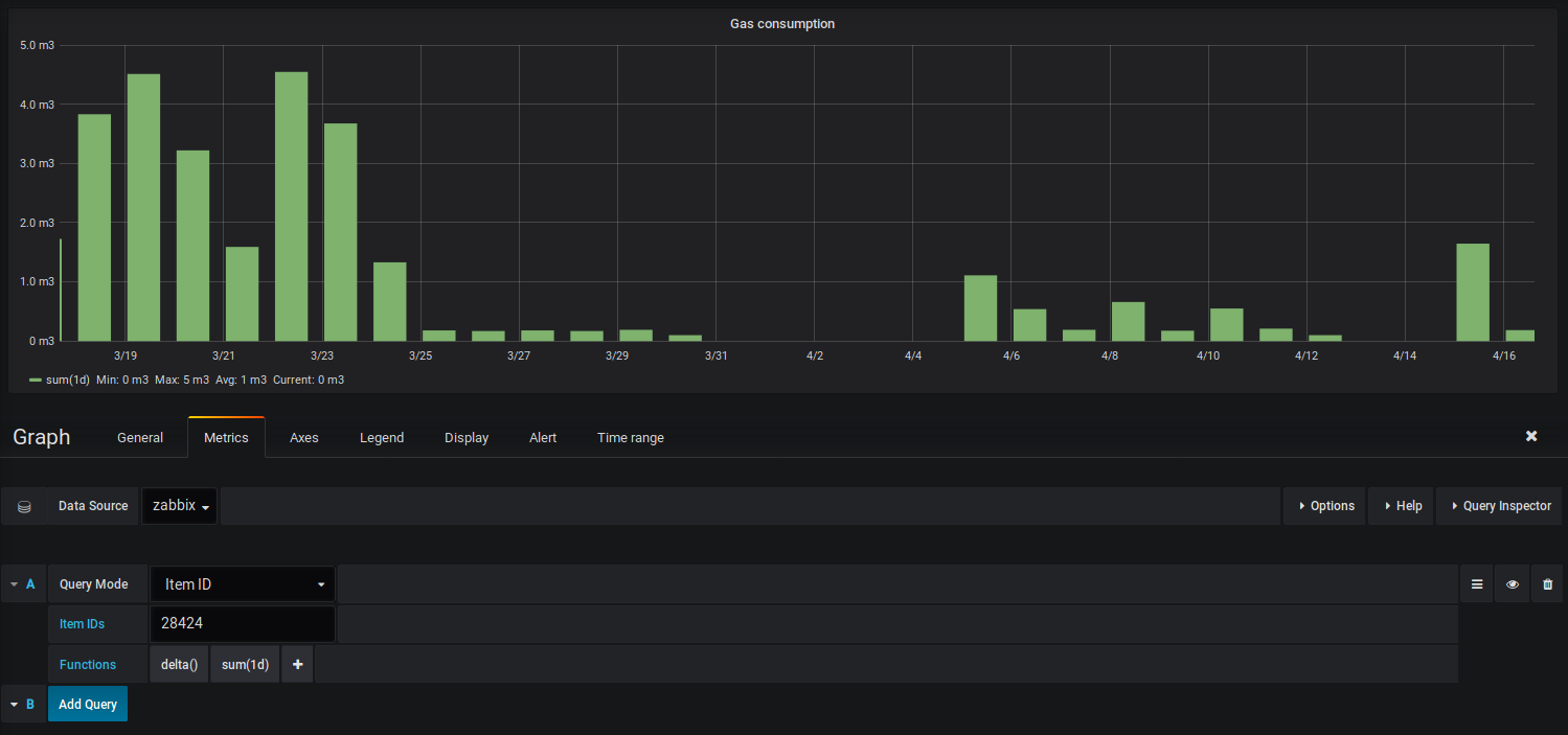 To explain the data: March was cold so the heating was almost still on; on 25th I left home and turned the heating off; on 31th my server crashed; on 5th I returned home so the value is sum for previous days without data, April was warm so I didn’t use central heating at all, I only used hot water and on 13th the server crashed again (without me noticing).
Smart electricity meter
I was very happy with the result so I built one for electricity metering too. I’ve had digital meter installed in my fuse box so it was only matter of preparing another board, disabling debounce (because it has nice sharp edges on pulse output) and connecting it:
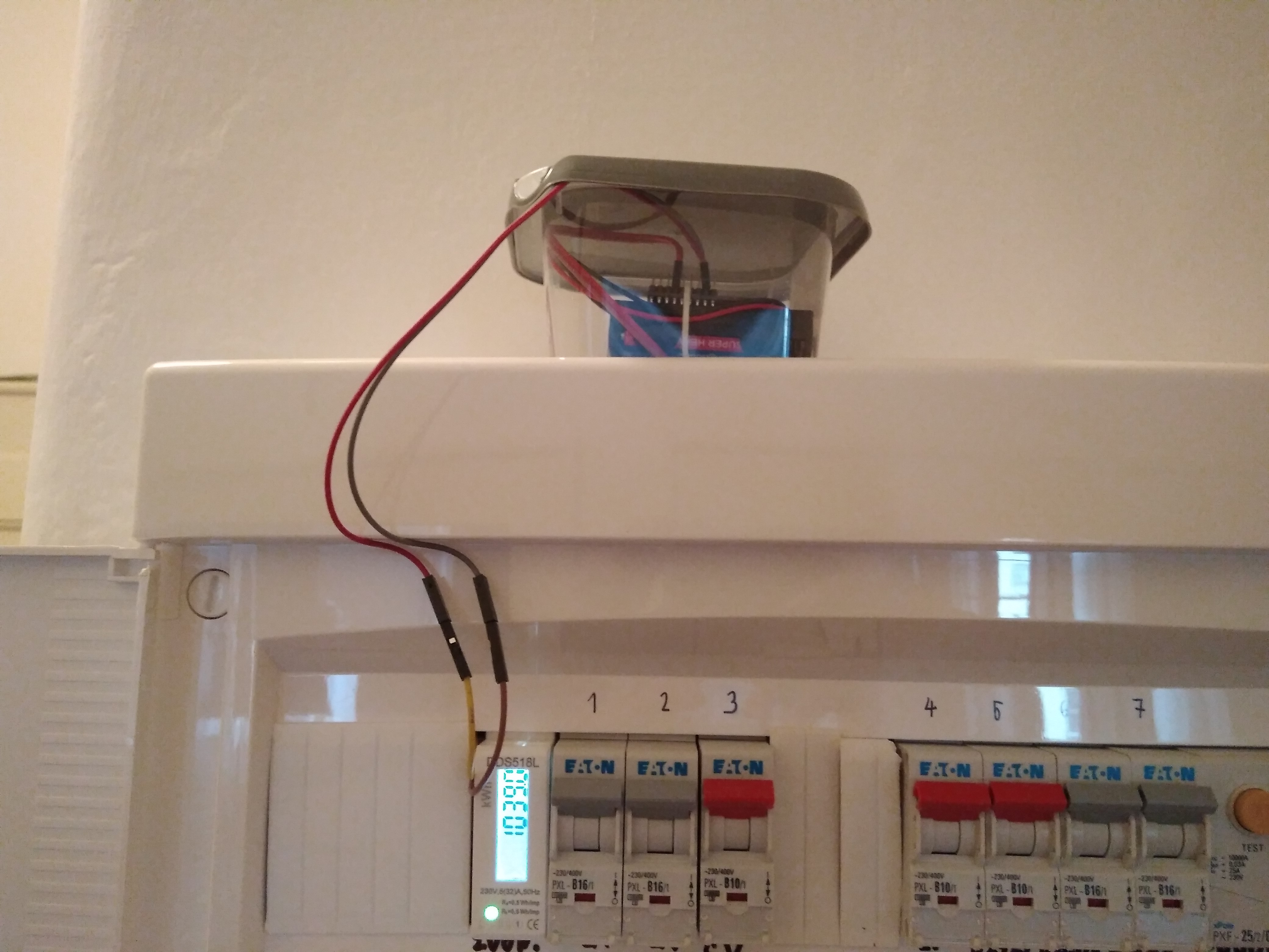 This allows me to debug and optimize my home actual power consumption.
 Now I am very interested how long will these two meters last on battery. I’ll post an update after batteries die.
At the end I want to mention this blog:
It kept me believing it has to be possible to make the module work when I had absolutely no hopes.
If you are reading these lines I’m glad my post interested and maybe inspired you. Looking forward to your comments.
Bye!
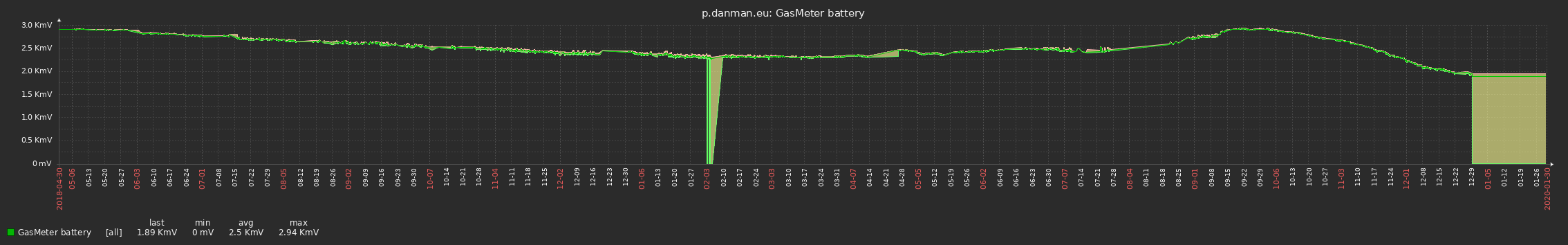
Update on power consumption
After 21 months (16. 03. 2018 – 29. 12. 2019), batteries have died. You can inspect power consumption on following graphs. Interesting is the increase before finally dying but it definitely meets my requirements for stamina.
Hello, very interesting post.
It is not clear for me, at the end, have used the expansion board in the box?
can you share the data format?
I am thinking of the same (gas counter) to send data into domoticz.
The expansion board was used only for developing, it’s not inside the final product. On this picture you can see everything what’s used in “production”: https://blog.danman.eu/wp-content/uploads/2018/04/IMG_20180316_155349_HDR.jpg
Data format is simple json: https://github.com/danielkucera/ble-meter-mbed/blob/master/src/main.cpp#L114
What is the circuit for the smart electricity meter? Are you using LDR to detect the blinking LED of meter? Is the source code available? How is battery life affected?
Thanks for your project.
I used magnetic contact for detecting pulses, source code is here: https://github.com/danielkucera/ble-meter-mbed (but it doesn’t compile anymore 🙁 ). You can see battery consumption for the last year here: https://blog.danman.eu/wp-content/uploads/2019/05/gas-meter-battery-1y.png
Thanks, is the chart for gas or electricity? Was the same circuit design used for both gas and electricity meters?
For gas. Yes.
Hello,
I’m trying to measure electricity with the same meter (DDS518L), but I’m not getting any pulses. I’m using Wemos D1 MINI and I have connected output pin 20 to D1 pin on Wemos and output pin 21 to ground on Wemos. I’m using Tasmota built in Counter functionality. Any ideas?
What sensor are you using? How did you attach it? What do you mean by pin 20 and 21?
There are two outputs on the electricity meter you have on the picture. They are marked as 20 and 21. See this image: https://ae01.alicdn.com/kf/HTB1ZIbibL1H3KVjSZFHq6zKppXao/DDS518L-120-230.jpg
And I connected pin 20 to D1 (GPIO5) on Wemos and pin 21 to GND on Wemos.
board = bbcmicrobit hasn’t stlink uploader (https://docs.platformio.org/en/stable/boards/nordicnrf51/bbcmicrobit.html). Add stlink to json board file \.platformio\platforms\nordicnrf51@3.5.0\boards\bbcmicrobit.json doesnt help. upload work, but any new BL devices on the air ..
“name”: “BBC micro:bit”,
“upload”: {
“maximum_ram_size”: 16384,
“maximum_size”: 262144,
“protocol”: “cmsis-dap”,
“protocols”: [
“cmsis-dap”,
“mbed”,
“stlink”
]
},