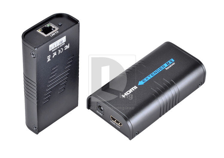
Short time ago, I was searching for a way how to get HDMI output from camera to PC (and then stream on the Internet). There are PCI-x HDMI input cards on the market, but they cost 100$+. Suddenly, I have found a device, which transmitted HDMI signals over IP network for half of the above price so I took the chance. Specification said something about MJPEG so I thought it might be possible.
Beginning
When the package arrived, first thing was to test if it really works as described and it really did – audio and video output from DVD player transmitted through common ethernet switch to my TV. Second thing I did was of course starting wireshark and sniffing the data.
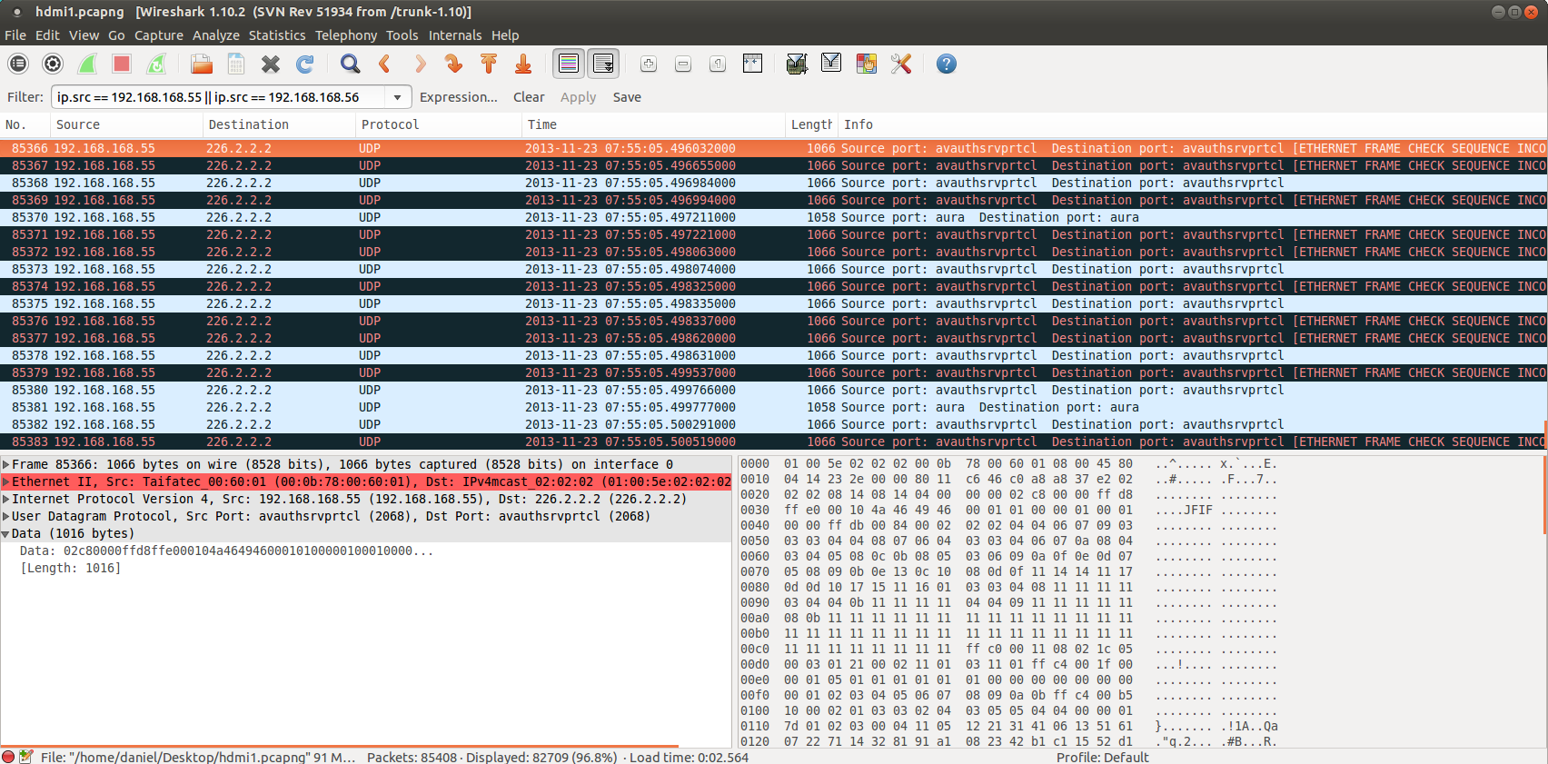
I found out, that it uses multicast to two UDP ports (2068 and 2066) and time to time broadcast some control packets.
Extracting video frames
Highest bitrate was on port 2068 what indicated it is video stream. After a while I found a packet with JFIF header (on picture above) – great! data is not encrypted, nor compressed and contains JPEGs. After investigating packets in sequence, I found out following structure in UDP payload:
| 2B – frame number | 2B – frame chunk number | data |
* frame number – (unsigned int, big endian) all chunks within one JPEG have same frame number, increments by 0x01
* frame chunk number – (unsigned int, big endian) first image chunk is 0x0000, increments by 0x01, last chunk has MSB set to 1
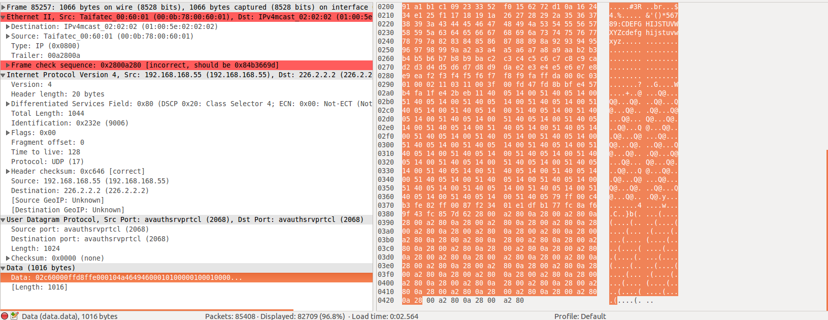
So I searched google for python multicast listener and modified it to save data to .jpeg files according rules above. After running, I was able to see some images with correct size but they were somehow damaged. First few pixels were OK but then there was a mess, like something was missing. Few hours I elaborated with capturing script what could be wrong but then I’ve got an idea: why does wireshark shows malformed packets? After looking on wireshark packets again, I found out, there are some bytes in the end of packet not part of UDP payload.
So I googled raw socket listener (thanks Silver Moon) and manually parsed IP and UDP headers to match correct packets and extract UDP payload with trailing bytes any voila! it worked, I’ve got correct JPEG frames.
#!/usr/bin/python

#Packet sniffer in python
#For Linux - Sniffs all incoming and outgoing packets :)
#Silver Moon (m00n.silv3r@gmail.com)
#modified by danman

import socket, sys
from struct import *
import struct

#Convert a string of 6 characters of ethernet address into a dash separated hex string
def eth_addr (a) :
  b = "%.2x:%.2x:%.2x:%.2x:%.2x:%.2x" % (ord(a[0]) , ord(a[1]) , ord(a[2]), ord(a[3]), ord(a[4]) , ord(a[5]))
  return b

#create a AF_PACKET type raw socket (thats basically packet level)
#define ETH_P_ALL    0x0003          /* Every packet (be careful!!!) */
try:
    s = socket.socket( socket.AF_PACKET , socket.SOCK_RAW , socket.ntohs(0x0003))
except socket.error , msg:
    print 'Socket could not be created. Error Code : ' + str(msg[0]) + ' Message ' + msg[1]
    sys.exit()

sock = socket.socket(socket.AF_INET, socket.SOCK_DGRAM, socket.IPPROTO_UDP)
sock.setsockopt(socket.SOL_SOCKET, socket.SO_REUSEADDR, 1)
#sock.bind(('', 2068))
# wrong: mreq = struct.pack("sl", socket.inet_aton("224.51.105.104"), socket.INADDR_ANY)
#mreq = struct.pack("=4sl", socket.inet_aton("226.2.2.2"), socket.INADDR_ANY)
#sock.setsockopt(socket.IPPROTO_IP, socket.IP_ADD_MEMBERSHIP, mreq)

sender="000b78006001".decode("hex")
notopen=1
# = open('/tmp/fifo', 'w')

# receive a packet
while True:
    packet = s.recvfrom(65565)

    #packet string from tuple
    packet = packet[0]

    #parse ethernet header
    eth_length = 14

    eth_header = packet[:eth_length]
    eth = unpack('!6s6sH' , eth_header)
    eth_protocol = socket.ntohs(eth[2])

    if (packet[6:12]==sender) & (eth_protocol == 8) :

        #Parse IP header
        #take first 20 characters for the ip header
        ip_header = packet[eth_length:20+eth_length]

        #now unpack them :)
        iph = unpack('!BBHHHBBH4s4s' , ip_header)

        version_ihl = iph[0]
        version = version_ihl >> 4
        ihl = version_ihl & 0xF

        iph_length = ihl * 4

        ttl = iph[5]
        protocol = iph[6]
        s_addr = socket.inet_ntoa(iph[8]);
        d_addr = socket.inet_ntoa(iph[9]);

        #UDP packets
        if protocol == 17 :
            u = iph_length + eth_length
            udph_length = 8
            udp_header = packet[u:u+8]

            #now unpack them :)
            udph = unpack('!HHHH' , udp_header)

            source_port = udph[0]
            dest_port = udph[1]
            length = udph[2]
            checksum = udph[3]

            #get data from the packet
            h_size = eth_length + iph_length + udph_length
            data = packet[h_size:]

            if (dest_port==2068):
              frame_n=ord(data[0])*256+ord(data[1])
              part=ord(data[3])
              print "frame",frame_n,"part",part, "len",len(data),"end?",end
              if (part==0) & notopen:
                 f = open('files/'+str(frame_n)+"_"+str(part).zfill(3)+'.jpg', 'w')
                 notopen=0
              if notopen==0:
                  f.write(data[4:])
Thank you chinese engineers! Because of wrong length in IP header (1044) I have to listen on raw socket!
Initiating stream
All this was done, when both sender and receiver were plugged into network. I also wanted to be able to use only sender and PC. When I plugged in sender only, no stream was broadcasted so I plugged in also the receiver a captured control frames. Each one control packet from receiver was unique so I took payload from the first one and sent it from PC to IP address of sender and I was successful. The sender started to send stream for a few seconds and then stopped. So I started to send control packets one per second and the stream was playing continuously. Then I experimented with length of payload – I started to send shorter frames and I finally found out, that it only needs a few specific bytes. So the final packet is as follows:
unicast to 48689/UDP with payload 0x5446367A600200000000000303010026000000000234C2
Extracting audio
Last part of my research was to extract audio from stream. Again, I used wireshark to sniff and analyse packets.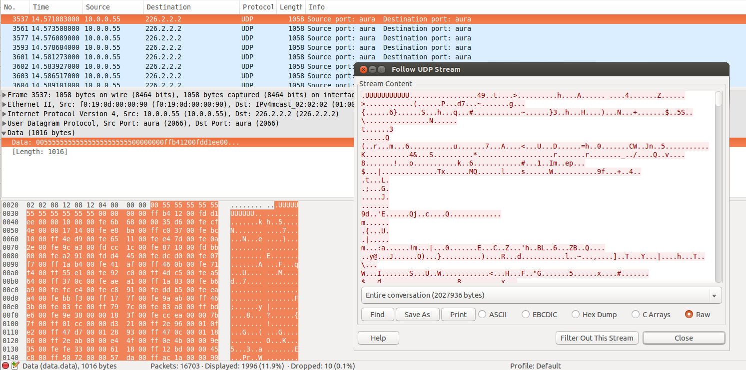
I saved the stream to file as raw data and imported into audacity. After trying few formats for importing I found out, that there is some audio playing when set for Signed 32bit PCM, big-endian, stereo, 48Khz.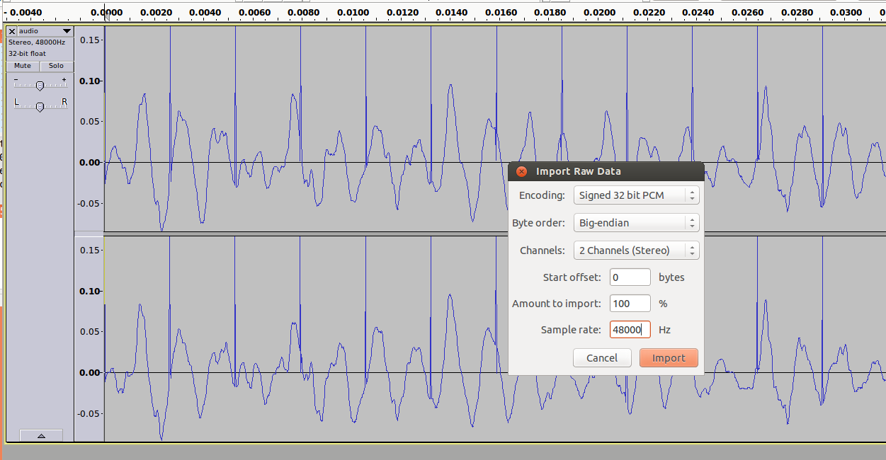
As you can see on the picture, sound was interfered by regular peaks. After investigating packets, I found that the data is well structured except the beginning of payload starting with some 0x00 and 0x55 (as on picture from wireshark). So I took python multicast listener again and truncated first 16bytes from each packet and streamed to stdout:
#!/usr/bin/python

import socket
import struct
import sys

sock = socket.socket(socket.AF_INET, socket.SOCK_DGRAM, socket.IPPROTO_UDP)
sock.setsockopt(socket.SOL_SOCKET, socket.SO_REUSEADDR, 1)
sock.bind(('', 2066))
# wrong: mreq = struct.pack("sl", socket.inet_aton("224.51.105.104"), socket.INADDR_ANY)
mreq = struct.pack("=4sl", socket.inet_aton("226.2.2.2"), socket.INADDR_ANY)
sock.setsockopt(socket.IPPROTO_IP, socket.IP_ADD_MEMBERSHIP, mreq)
counter=0

while True:
  packet=sock.recv(10240)
  sys.stdout.write(packet[16:])
I started vlc to listen to streamed audio with following command:
./listen-audio.py | vlc --demux=rawaud --rawaud-channels 2 --rawaud-samplerate 48000 --rawaud-fourcc s32b -
and I’ve got audio playing from VLC.
Hardware
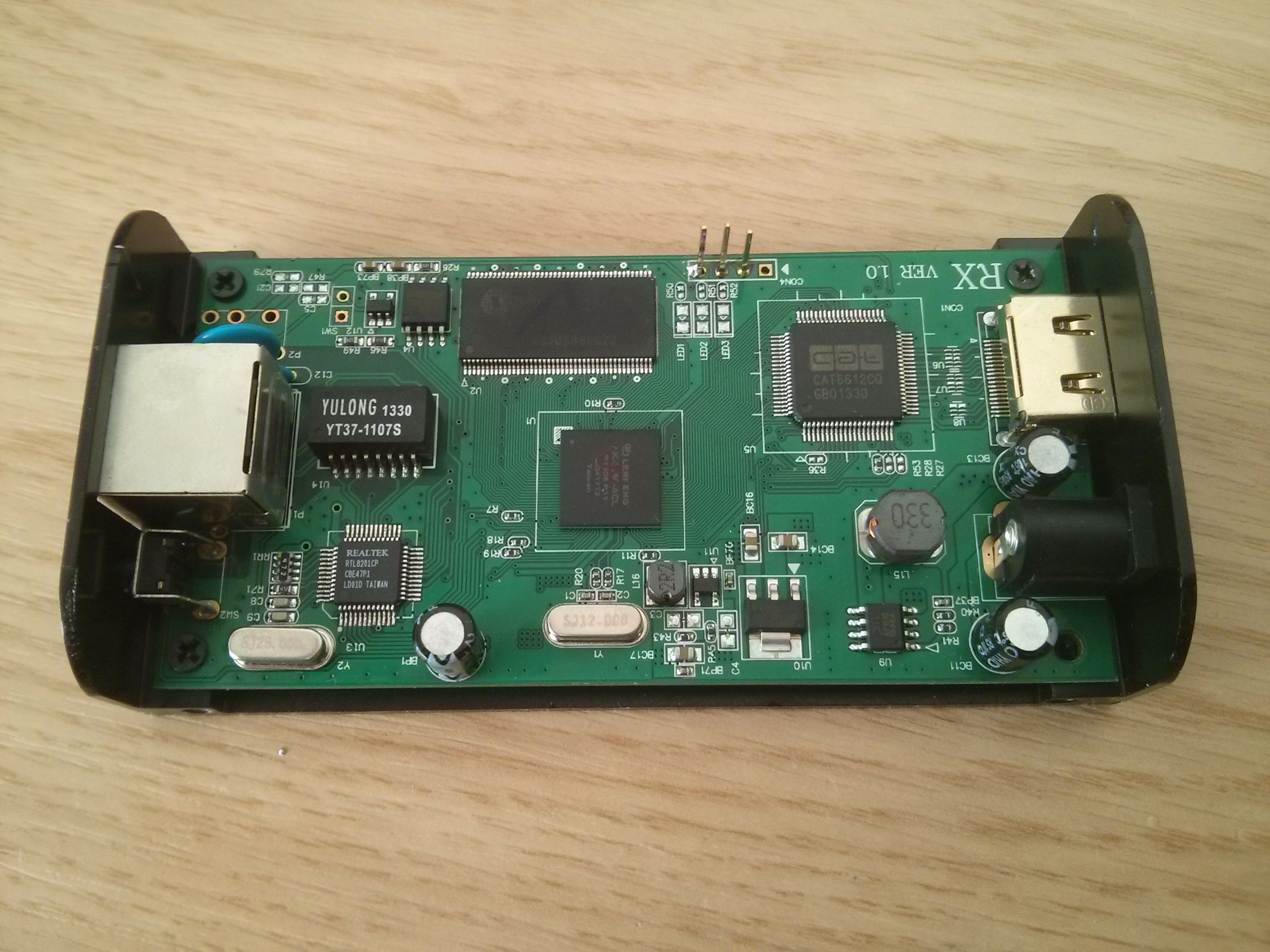
Great magic box! As a curious engineer, I definitely had to know what’s inside this gadget. Here are some photos:
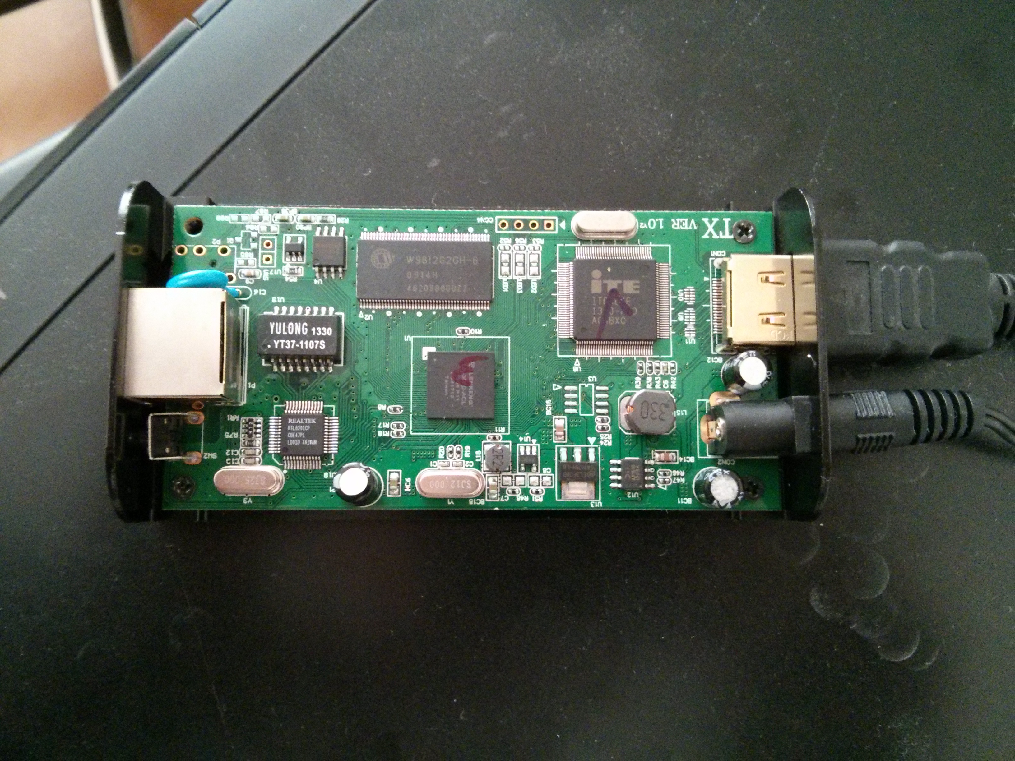
- LK-3080-ACL – main processor from Lenkeng
- IT6604E – HDMI input interface doing HDCP decoding
- LK-3080-ACL – main processor from Lenkeng
- CAT6612CQ – HDMI out interface
Conclusion
I was searching for solution for live video mixing from cameras with HDMI output. They can be far from mixing computer connected via switches and cheap ethernet technology. With this knowledge I have build a prototype for mixing software in Qt separating input video streams by source IP and mixing/switching them. It’s still in beta phase, but you can see it on my github. If you have any questions or suggestions, feel free to let me know in comment.
Quality test (updated 26/01/2014)
As requested by readers, today I did a speed/quality test. I took jpeg 1080×1920 image and let it play on DVD player. You can compare original and transmitted image here:


Transmitter was streaming 1080p@18fps with 90Mbps bitrate. Unfortunately I have no blue-ray player on hand to test original HD content.
Update 2. Feb 2014
Today I have quickly tested 1080 again and it showed up, that quality is not that bad as on pictures above. Please see following picture. The source was computer showing the same picture in fullscreen mode.

Update 23. May 2014
Together with Tom Warren we modified the script in a way that now it plays correctly in VLC via pipe using this command and code:
./scriptname.py | vlc –
#!/usr/bin/python2

#Packet sniffer in python
#For Linux - Sniffs all incoming and outgoing packets :)
#Silver Moon (m00n.silv3r@gmail.com)
#modified by danman


import socket, sys
from struct import *
import struct
import binascii


#Convert a string of 6 characters of ethernet address into a dash separated hex string

def eth_addr (a) :
  b = "%.2x:%.2x:%.2x:%.2x:%.2x:%.2x" % (ord(a[0]) , ord(a[1]) , ord(a[2]), ord(a[3]), ord(a[4]) , ord(a[5]))
  return b


#create a AF_PACKET type raw socket (thats basically packet level)
#define ETH_P_ALL    0x0003          /* Every packet (be careful!!!) */
try:
    s = socket.socket( socket.AF_PACKET , socket.SOCK_RAW , socket.ntohs(0x0003))
except socket.error , msg:
    print 'Socket could not be created. Error Code : ' + str(msg[0]) + ' Message ' + msg[1]
    sys.exit()


sock = socket.socket(socket.AF_INET, socket.SOCK_DGRAM, socket.IPPROTO_UDP)
sock.setsockopt(socket.SOL_SOCKET, socket.SO_REUSEADDR, 1)
#sock.bind(('', 2068))
# wrong: mreq = struct.pack("sl", socket.inet_aton("224.51.105.104"), socket.INADDR_ANY)
mreq = struct.pack("=4sl", socket.inet_aton("226.2.2.2"), socket.INADDR_ANY)
sock.setsockopt(socket.IPPROTO_IP, socket.IP_ADD_MEMBERSHIP, mreq)


sender="000b78006001".decode("hex")
#sender = binascii.a2b_hex("000b78006001")  bc5ff4730e6f
#sender = binascii.a2b_hex("bc5ff4730e6f")
#print binascii.b2a_hex(sender)
notopen=1
# = open('/tmp/fifo', 'w')
print "--myboundary\nContent-Type: image/jpeg\n"

# receive a packet
while True:
    packet = s.recvfrom(65565)

    #packet string from tuple
    packet = packet[0]

    #parse ethernet header
    eth_length = 14

    eth_header = packet[:eth_length]
    eth = unpack('!6s6sH' , eth_header)
    eth_protocol = socket.ntohs(eth[2])


    if (packet[6:12] == sender) & (eth_protocol == 8) :

        #Parse IP header
        #take first 20 characters for the ip header
        ip_header = packet[eth_length:20+eth_length]

        #now unpack them :)
        iph = unpack('!BBHHHBBH4s4s' , ip_header)

        version_ihl = iph[0]
        version = version_ihl >> 4
        ihl = version_ihl & 0xF

        iph_length = ihl * 4

        ttl = iph[5]
        protocol = iph[6]
        s_addr = socket.inet_ntoa(iph[8]);
        d_addr = socket.inet_ntoa(iph[9]);

        #UDP packets
        if protocol == 17 :
            u = iph_length + eth_length
            udph_length = 8
            udp_header = packet[u:u+8]

            #now unpack them :)
            udph = unpack('!HHHH' , udp_header)

            source_port = udph[0]
            dest_port = udph[1]
            length = udph[2]
            checksum = udph[3]

            #get data from the packet
            h_size = eth_length + iph_length + udph_length
            data = packet[h_size:]

            if (dest_port==2068):
              frame_n=ord(data[0])*256+ord(data[1])
              part=ord(data[2])*256+ord(data[3])
              if (part==0) : # & (notopen==1) :
                 #f = open('files/'+str(frame_n)+"_"+str(part).zfill(3)+'.jpg', 'w')
		 #fname = str(frame_n)+"_"+str(part).zfill(3)+'.jpg'
		 #fname = 'file.jpg'
		 print "\n--myboundary\nContent-Type: image/jpeg\n"
                 notopen=0
		 #print 'File ' + str(frame_n) + ' created.'
              if notopen==0:
                 #f.write(data[4:])
		 #print data[4:]
		 sys.stdout.write(data[4:])
		 #with open(fname, 'wb') as fin:
		    #sys.stdout.write(fin.write(data[4:]))
		    #print fin.write(data[4:])
Update 13. Dec 2014
For those who are interested in Windows version, Brian has written .NET version of similar capturer from scratch with a nicely documented project page here.
Brian, thank you for your work.
Update 1. Oct 2020
Yes, this is an update after 6 years. I guess nobody is interested in this device anymore, but I want to sum up some information from comments here and give news about the device.
There is a serial interface on pin header CON4 with following pinout:
1 = +
2 = Rx
3 = Tx
4 = Gnd
You can find the list of possible commands in this comment.
A comprehensive quality evaluation can be found in another comment.
There is a webinterface on standard port 80, where you can set IP address, EDID, Serial settings and upgrade firmware.
The firmware consist of two parts: bootloader and the main program. You can find full dump of the SPI flash on this link.
There is a newer revision of the device which doesn’t have the packet length bug (which causes you need to listen on RAW socket). I’ve written a simple capture software in Go, there are precompiled binaries for Linux and Win.
Over the time the device was sucessfully reverse engineered and an opensource firmware is available.
Thanks to this effort, also the packet length bug has been binary patched and you can find the patched firmware here.
At 1080p it transmits only 17-18FPS to fit into 100Mbit limit.
The latency can be seen in this video:
You can find datasheet of the main chip here:
In general, this device is still okay if you just need JPEG frames out of your video or very short latency. If you need better compresion, I recommend you to look elsewhere, e.g.:
Awesome … good job
thanks for releasing this
Congratulations! Amazing project and some nice hackery right there. I was thinking for a long time about disk recorder for HDV camcorders. They use firewire for data transfer. It would be easy if you can find small device with FW port and linux OS but it looks like it’s almost impossible – there are no compact devices, small enough to mount in on the camera.
Your article inspired me to think differently – why use Firewire if we have HDMI present on almost every camcorder? HDMI recorders are also expensive, even HDMI capture cards are out of my price range (not to mention you can’t build small device around it).
But what if we use one of those HDMI extenders, hook it up to the Raspberry Pi and capture all data to the SD card? It would be simple, small and battery powered – perferct for my application.
From my understanding you get continous audio stream and every video frame as a separate JPEG file, right? It might be possible to use ffmpeg to compress it with h.264 and write video and data together as a single file (h.264 or maybe less lossy format).
Yes, you are right. Of course, you can take this stream and push it to ffmpeg but this was not my original intention.
For my application image quality is on the first place. I see there is huge quality loss but it might be caused by DVD player (note moire patterns and serration on “teeth” on the edges, typical to scaling down by line skipping). Do you have other device with HDMI port? Some camcorder so you can record footage by the camcorder itself and via HDMI extender then compare.
Won’t work with a raspi -> this thing makes data at about about 90 MB/s, (90% of a gigabit ethernet connection) and you’ll neither get that into (or out of) a Raspi, which only does about 18 MB/s at best via usb, and only has 100 mbit ethernet hanging from the USB., so only good for maybe 10% of what you’d need.
You **might** get it done with a hardkernel odroid, if you pick one with both USB3 (for a fast hard drive) as well as gigbit ethernet – the Odroid XU4 might work.
Hold on, wait a sec – are these things only 100 mbit? or gigabit?
In which case you just might squeeze it into/outof a raspi after all.
(both ethernet adaptor and disk have to live on the same USB 2.0 root hub, which in my benchmarks under ideal conditions doesn’t do much better than 18 MiB/s)
Hmm. HDMI is about 5 gigabits, and specifies about 4 gigabits for 1080p@60.
The MJPEG encoding certainly has its work cut out.
Nice job! How reliable is this device — can you leave it streaming for 24 hours, for example?
Thank you, I haven’t tried continuous streaming for such a long time but when I left it conected and powered on for a week, it retained fully functional.
Could you post some high res pictures and what was on the debug port? I see you connected some pins to it.
Did you find anything interesting on that serial port on CON4?
I have used usb to ttl serial converter but I was not able to cummunicate without errors so I gave up. I’ve got some output but the communication was somehow crippled. Maybe I’ll try again later with some other converter. So far I have found it is some sort of debug console.
Show me such communication. Or try again usign a proper shield and SHORT cables. Usual speed is 57600 8n1 or 115200 8n1 but there can be variations.
I have received the device as well and hooked up my jtagulator to the device.
It’s
1 = +
2 = Rx
3 = Tx
4 = Gnd
using 3.3v
When I send an enter rn it sends back
Unknown Command!!
TFCMD>
So I am looking into that currently.
try HELP 🙂
Typing help gave me an item.
reg : Read/Write reg. of taifa device
sys : Do some system set
spi : Read/Write SPI device
osd : Read/Write SPI device
gpio : GPIO port Read/Write
mdio : Read/Write mdio device
i2c : Read/Write i2c device
hdmi : Read/Write HdmiTx device
hdmi : Read/Write HdmiRX device
dbg : Debug message level
ch : Audio buffer control
i2cm : Read/Write i2c device with multi register address
edid : EDID Read/Write
3 : Do EP9x53 controller Task
i2s : T/R audio by I2S mode
l2 : Set L2 routing table.
l4 : Set L4 routing table.
sdram : External SDRAM Test
cap : Capturer fskp, CRC, bypassSD, shsize, svsize
ver : Debug Console Version Information
av : select Tx/Rx format
q : video quality toggle
q : show stack status
fps : show/off fps for test
inband : inband packet test
TFCMD>
the “av” command is very important.
what options does it have?
probably changing the format is the easier route to follow.
Boot sequence:0123456
*************************************************
* Initializeing MM *
*************************************************
Start:0x00100000 End:0x00280000, Size:0x00180000(1536K), Pages:384
TF680 FW Verion: Tx_v1.07_C904 ITE 152MHz IR LAN_MODULE
FW Release Date: Nov 2 2012, 11:04:55
TF680 MAC: 00:0B:78:
TF680 IP: 192.168.168.55
All of Tasks Created
[taifa Debug Console]
(c)2010 taifatech inc. All rights reserved.
**Type ‘help’ for more details; ‘exit’ to quit**
TFCMD>
OtoM TFVEP is disconnected !!!
So here are some commands and their results.
TFCMD>reg
WARNING: too few parameters…
USAGE:
reg r 90907000 10: read sequentially from reg 0x90907000 len.0x10
reg w 90907000 aa55aa55 55aa55aa: write 0xaa55aa55, 0x55aa55aa to reg 0x90907000.
reg f 90907000 aa55aa55 20: write 0xaa55aa55 from reg 0x90907000 to reg 0x9090701f
reg e : enable/disable message output of wirte operation
TFCMD>edid
WARNING: too few parameters…
USAGE:
edid r 2 : Read EDID content of HDMI Port 2
edid w 2 5 : Write EDID 5th content to EPROM for HDMI Port 2
HDMI EDID : PortI – 5th; PortII – 6th
TFCMD>sdram
WARNING: Unknown Option…
USAGE:
sdram d startAddr endAddr: SDRAM Data Bus Test
sdram v baseAddr byteLen: SDRAM Device Test
sdram s startAddr endAddr: Scan All SDRAM Test
TFCMD>ver
Debug Console Version Information
version:0.2
TFCMD>av
WARNING: too few parameters…
USAGE:
(for demo only)
av [video mode=>1:1080p, 2:720p]
3:960×600
4:960×544
5:960×536(1/2 scale down)
6:1267×728(2/3 scale down)
7:1440×1080(source 1080p 3/4 scale down)
8:960×544(source 720p 3/4 scale down)
9:JPEG Encoder 420 format
TFCMD>q
q p [n]: paper quality)
q d [n]: default quality)
n: 0 ~ 24(18h), 0 is best, and 24 is worse
TFCMD>fps
WARNING: Unknown Option…
USAGE:
fps show : show fps
fps off : off fps
TFCMD>inband
WARNING: Unknown Option…
USAGE:
send : send test data
TFCMD>
I have see this. I’d be great if they send us technical datasheet. I asked them but it looks like they don’t won’t to release such documents.
q p 0
q d 0
av 0
All commands so far has been from the sender.
Command “q” is what we should modify. Did you tried to set it for the best quality? Can you post some sample footage?
I took some time to find some sort of service manual for these devices. It looks like SoC is Taifatech TF-680. I couldn’t find any helpful files tho. It looks like these devices have Web control panel so type its IP address to the web browser.
It has web interface but it allows only firwmare upgrade, EDID info upload and IP change.
Not yet, I haven’t even connected an hdmi cable or network cable.
I will not have time today to do so, but I could do that tomorrow evening and post some results.
I’d be thankful for checking what real quality looks like and see if “q” command actually does something. I’m about to order this device myself but I must be sure the quality meets standards for my application.
http://www.taifatech.com/tf680.htm
😀
I have see this. I’d be great if they send us technical datasheet. I asked them but it looks like they don’t won’t to release such documents.
To complete your work you should create 2 stand-alone programs: one to receive (i.e. record) and one to send (i.e. playback) video streams with optional conversion to mpeg 😀
Good suggestion but I’m too lazy to do things I do not need 😀 . I can sell you the reciever and you can continue with the second part 🙂
LOL! I’m lazier than you 🙂
After inspecting the device I think it’s even expensive for the low quality of the streams it outputs.
Never mind, they are high res, my other question still stands.
There’s an open question being debated on Hackaday about bandwidth vs. quality of these devices. Given that it’s only a 100Mbps port and using MJPEG, there is going to be a definite limit on quality.
Are you able to provide some bandwidth-usage number (i.e. how close to the max 100Mbps does it get?) as well as some 1080 screenshots of “clean” content, e.g. from a Blu-ray player. That would also answer the HDCP question too 😉
Thanks!
Please see updated text.
There does seem to be some fairly significant loss of quality in your pictures.
Those who want high quality will probably do better when a high quality HDMI capture card.
That said, this does a very good job considering it’s 1/2 the price and gives you a free receiver to view the content as well.
I’d hold on expressing opinions on image quality. Look carefully on the picture. It looks like the image was scaled down and than scaled up. Maybe his DVD player is doing that conversion. Let’s wait for sample footage from other video source.
My advice is to use camcorder with HDMI out to see what quality camcorder records and what quality can be achieved via HDMI capture. Another good device to test would be a PC with HDMI on the GPU: record computer screen via HDMI extender and do a print screen and then compare.
Yes, I will test it with PC output during weekend.
Please see updated text. I seems you were right 🙂
Where can i buy one of this?
Does it have the model / manufacturer?
Is it available in something with easy international shipping like dx.com aliexpress other than ebay?
I can offer you some hdmi extender at low price.
http://www.hdgenius.net/HD373-HDMI-over-cat6-cat5e–lan-unlimited-Extender-with-splitter-function_p113.html
Interested in knowing if the unit streams a constant framerate regardless of the input resolution or does it use the input resolution to determine the framerate?
I am involved with running conferences and these would be perfect if we could feed the MJPEG stream into something like GStreamer so we can feed it into our mixing software.
There is an option to overlay the FPS with the serial console, I will overlay this Wednesday and see if it is constant or fluctuating too much.
My goal is to record it and replay it over an blackmagic device.
What I also saw was that it de-interlaces it, so 1080i 5994 in, will result in 1080p60 probably.
Huuf: Can you contact me at hdxx@o2.pl? I have some questions to ask. I could ask you here but e-mail is more convenient since you don’t have to visit the website.
So, what do you think is the best and cheapest way to record an HDMI stream? This device is too low quality.
The best HDMI capture device I have ever used was made by Blackmagic, I used the H.264 pro (which is £325) for my work but their other kit is also good. If you can use PCIe then their capture cards are well priced. The problem is that HDCP doesn’t work on these cards.
I’ve bought one of these kits to see how they perform for myself.
Great! The quality loss is not that significant, exactly as I predicted 🙂 I’m curious if it can be even better if we play a little bit with the console.
Manufacturer replied to my first message but then they stopped. I asked them about SDK which would allow us to write new firmware, possibly with USB support (TF-680 has USB host!) for WiFi dongles which would give us better transfer and maybe better quality. It has many more cool features but without SDK we aren’t going to make anything…
Do you have ideas how we can obtain one?
Great beat ! I wish to apprentice while you amend your site, how could i subscribe for a blog website? The account aided me a acceptable deal. I had been tiny bit acquainted of this your broadcast offered bright clear concept
Thinking further on this, why don’t you convert your HDMI receiver into a gstreamer source? Then you can just build your switcher/matrix/mixer around gstreamer and then you have flexibility for your sources? It seems building in the hardware to your design would limit it?
I could, but I want to have complete controll on all parts so I can do some optimizations. Next thing is, that I wanted to avoid any external utilities which can introduce unwanted buffering/latency.
So, I did some research on the unit this week during the evenings and this morning.
In short: Don’t buy it. Not that reliable.
In long:
I used the following equipment:
-Sony BDPBX39 Blu-ray player outputting at 1080p60
-Philips 22pfl4505d/f7 – TV – Maximum input 1080i60
Audio quality:
-Audio is in good quality, as stated before, most people won’t hear the difference, but it is 2 channels only, so if you have this extender in between and do want to do multi channel 5.1 surround sound you will unable to do this.
Video quality:
-It is OK for JPG, encoding quality seems OK, when in high detail shots you see the degradation but meh.
-It does do de-interlacing on chip, so if you have an interlaced signal, you will get an de-interlaced signal into the receiver instead of just sending top or bottom field
-It appears to always downgrade to a maximum of 30 FPS (See Network for more details about FPS)
-The Rx end downgraded to 720p to make an progressive resolution to not deal with interlacing.
Audio/Video synchronization:
-BAD, it is easy visible that the audio is out of synchronization and never appears to be corrected. In the capture program you would need the ability to sync up audio / video.
Network quality with NetGear GS105
-Test environment where it goes just from Tx –> Netgear –> Rx, no other network devices attached to the NetGear using 3 feet Cat6 cable
-There are a lot of dropped frames, it rarely gets to 30 fps, but is mainly arround 13-17fps, often it drops to 0 fps and only audio passes through where it stopped completely twice.
Network with direct Cat6 cable (3 feet)
-Mainly remains at 30FPS, sometimes there is a drop, where it says 1 has failed, but actually 2 frames are missing.
Extra research
-Packet at port 48689 (all values are hex, unless otherwise specified)
–Receiver sends one when it receives one from the sender.
–Endianness is different in the packet counter than in the rest of the packets
–[0..4] 5 byte header [54:46:36:7a:63]
–[5] 1 byte define what you are
—01 = Sender
—02 = Receiver
–[6…7] always 00 00
–[8…9] 2 bytes of an internal counter of how many 48689 packages have been send. Overflows at ff ff back to 00 00 to 01 00
–[10..18] two different sequences for sender / receiver
—[00:03:03:03:00:24:00:00:00] = Sender
—[00:03:03:01:00:26:00:00:00] = Receiver
–[19…22] Uptime receiver in ms (0 for sender)
All bytes are 0 for the receiver from now on to make a length of 512 bytes
–[23…26] [00:00:00:00]
–[27] Some flag byte to indicate the signal
—03 for signal
—10 for no signal
–[28..29] Width of signal (probably input or encoded width)
–[30..31] Height of signal (probably input or encoded height)
–[32..33] FPS of signal
–[34..35] Width of signal (probably input or encoded width)
–[36..37] Height of signal (probably input or encoded height)
–[38..39] [00:78]
–[40..43] Uptime in ms for the sender
–[44..49] [00:01:00:00:00:00]
–[50] Some indicater of number of receivers connected but doesn’t change when one disconnects
—00 when none is connected
—02 when one is connected
–[51] [0a]
For the rest it’s filled with 00’s to pad up to 520 bytes.
-Packet on port 2067
–This is a frame count packet.
The rest of the details are already covered in this blogpost.
Can anyone help me?
Since I plugged the sender and receiver in the network the Wi-Fi connection of my laptop will not connect to the router anymore.
Any suggestion?
Thanks in advance.
Eric
Yes, this is normal if you are using non-multicast capable switches. They distribute multicast as broadcast and overload your wifi. You should use/test these convertors on separate subnet or somehow filter multicast on you wifi AP.
Great and entertaining work, even though I only understand half of it! Greeting from Mexico!
Hi Huuf
I want to use this device just to connect a PC to a long distance monitor (about 40 metres) at 1920x1080p resolution, mainly for powerpoint pesentations, means resolution is important.
You said that receiver downscales to 720p. Is it true for 1080p input content or just for interlaced ?
Thanks
Danman,
The jpeg file you captured at receiver is 737.460 bytes, means 5.9 Mbits
Then at 30fps will be 177 Mbits/s stream
So, How can this device broadcast 1080p at 30fps with a 100Mbit lan interface ?
I’m missing something ?
At 1080p it transmits only 17-18FPS to fit into 100Mbit limit.
But Huuf said this:
“Network with direct Cat6 cable (3 feet)
-Mainly remains at 30FPS, sometimes there is a drop, where it says 1 has failed, but actually 2 frames are missing.”
¿?
It’s very simple, they use link aggregation / trunk called
Turbo MII:
“Up to 200Mbps network speed via Turbo MII interface”
http://ww1.microchip.com/downloads/en/DeviceDoc/00001520A.pdf
“One MAC supports MII / Turbo MII “:
http://www.taifatech.com/files/TF-680_Product_Brief_04.pdf
Maybe they use 2×2 pairs of the Cat6 cables.
// Edit: maybe I’m wrong. The RTL8201 doesn’t support it!?
Here is PC client for their “wiplay” rotocol. May be there are some useful libraries here: https://cloud.mail.ru/public/156150a2630d/WiPlay_Win7_TF680_20121126_V1.1.10.rar
I’m not able to get the configuration packet (or any other packed but ‘who is’) from the receiver, nor its possible to send config packages to the receiver. Also, i’m not able to get an image with the mixer software. My devices have a label called “V 2.0”. I’m able to get the Jpeg pictures with the python script and both devices (sender & receiver).
Has something changed with a new hardware revision?
OK, it’s working
hey. I’ve updated your python script to work with gstreamer. It works quite well, but unfortunately depending on the content, the stream is broken. You also should have noticed that. Does somebody know a fix for that?
Heres the code:
http://codepad.org/Bb6K4Kxe
you can start it with this command as root (check the fps):
python udphdmi.py | gst-launch-1.0 -v fdsrc do-timestamp=truet ! ‘image/jpeg,framerate=30/1’ ! jpegdec ! autovideosink &
As you can see, I played a little bit with single file jpeg output and audio output. I’m searching for a way to easily multiplex video and audio to gstreamer. One idea is to split both into multipart messages, but that doesn’t work (gestreamer is able to find the header with multipartdemux, but it crashes). Maybe I’m too nooby ^^.
PS: you need a NIC that “likes” defective packages.
there’s one more bug in that script I fixed later, this line:
part=ord(data[3])
should be:
part=ord(data[2])*256+ord(data[3])
but it shows up only with bigger frames, maybe that’s your case.
i have to correct do-timestamp=truet ! into do-timestamp=true !
I’ve solved 1 Bug: first the part has to be calculated: part = data [2]*256 + data [3].
But the real problem seems to be lost packets. Wireshark is able to receive them, so they are not lost. Is it possible that the python script is to slow to receive all Packets?
Yes, it might be the case.
You might need to put the NIC into promiscous mode, or set the NIC-driver to pass on packets with checksum errors:
eg.
———–
import os
NIC=’eth0′
ret = os.system(“ifconfig ” + NIC + ” promisc”)
if ret != 0:
print ‘NIC could not be put in promiscous mode. Error.’
sys.exit()
else:
print ‘NIC (‘ + NIC + ‘) put in promiscous mode’
———-
as root…
see eg.
http://stackoverflow.com/questions/6067405/python-sockets-enabling-promiscuous-mode-in-linux
and
http://stackoverflow.com/questions/22101650/how-can-i-receive-the-wrong-ethernet-frames-and-disable-the-crc-fcs-calcul
Confirmed. I’m able to receive a real smooth stream with this update (on my smallest 1.4 Ghz core2duo machine):
http://codepad.org/L0v4hIJe
I’ve started it with that gstreamer command:
python bufferudp.py | gst-launch-1.0 -v fdsrc ! queue ! jpegdec ! autovideosink &
so, if someone has an idea, i would be very interested in audio and an even faster python skript.
(The Problem was, that gstreamer canceled the decoding. It was a simple timing problem. Removing the fixed framerate, cleaning up the skript and adding a buffer is all the magic)
OK, here it is:
socket.py:
http://codepad.org/VThPnCR5
and here the magic:
sudo python socket.py
and some gstreamer magic:
gst-launch-1.0 -v udpsrc port=5007 buffer-size=100000 ! queue ! audio/x-raw,rate=48000,channels=2,format=S32BE ! autoaudiosink udpsrc buffer-size=1000000 port=5006 ! queue ! jpegdec ! queue ! autovideosink
take care that there are no foreign packets @port 5006 or 5007
I still have some problems with some broken frames. If somebody has an idea, i would be very interested.
I have tested your python script.
Thanks for that.
But get this error.
‘module’ object has no attribute ‘AF_INET’
Ubuntu
Looking at the TF-680 datasheet, it suggests that upto 7.1 audio is supported in the chipset (presumably PCM only?), yet Huuf said (in comment 67) that it only outputs 2-channel. Can anyone else confirm whether the audio is downsampled to 2-channel?
I’m looking at using one of these to get an HDMI “input” into a dedicated server (i5-based) that can then transcode into H264, and stream to a set of Raspberry Pi units that I have behind all the TVs in my house (7 Pi in all) – is this achievable?
My source outputs 1080i50 or 720p50 – am I right in thinking that this device will deinterlace the 1080i50 to 1080p25, but then only deliver ~18fps of that?
Have ordered one, to see if I can make it work for what I need.
It occurs to me that it might be possible to use a Raspberry Pi to handle the transcoding from MJPEG to H264 in hardware using an up-to-date version of gstreamer. The only problem is that it’ll require a separate USB-ethernet device (because the built-in 10/100 will be busy with the stream from the Lenkeng).
Should be fun trying, anyway!
hi and thanks for the actual blog post ive recently been searching regarding this specific advice online for sum hours these days as a result thanks bgcdgacddccd
Hi many thanks for your work.
It’s first time I use python.
Could you let me know if can I transmit HDMI signals over IP network to mac os x PC?
Hello,
I think there should be no problem.
Could you explain me how can I proceed to insert the command in the python to achieve the transmission?
I’m trying to use the brillant work already done here to take the output (video and audio) and serve it up via RTP or similar for a software mixer (ie vidblaster or wirecast).
Best I’ve got so far is video in linux. Can’t get the mixer to work (it loads, but blank display for hdmi source) and no luck with TheRealTentacles scripts either…
Any ideas? Anyone keen to help ?
Didn’t get the sender to transmitt.
If I log with wireshark,
I got messages from Transmitter-device on port 48689.
But didn’t see the “activation” message from receiver.
any one a hint.
Have the most things done in C.
But this is not clear for me.
After sniffing the networktraffic, I think, they changed something in there FW.
Here what I found:
Transmitter is polling on port 48689 (UDP Packet).
When receiver is switched on, it seem’s that the receiver is sending a Broadcast
message. I saw the source IP was 192.168.168.56 (receiver), and target IP was 192.168.168.55 (transmitter).
I thought, this message (broadcast) will activate the streaming. But didn’t work.
Next message after this is a valid UDP message, on port 2067 as a “sync” Packet. Byte 5+6 is the count of the frame.
And then the already known UDP packets.
I never seen any other packet from receiver!
Any one how has also played arround with this extenders?
Did you see any different packets fom receiver?
Thanks
I’m seeing the same with newer-model transmitters – IP of 192.168.168.56, and polling over port 48689. If I add another transmitter to the same network, it lays claim to the exact same IP address and also starts sending UDP packets over port 48689.
My receiver must be faulty – do you mind posting the broadcast or sync message sent to the transmitter?
I saw this and bought a pair on eBay with an extra receiver. The units themselves are great, no longer having crappy video sender picture. I hope to also view the feed on the pc, there is lot of information here to absorb, maybe better suited to a GitHub project to bring it all together.
Great effort on all concerned with the reverse engineering ! ( just need to get WinLirc working with the STB for full remote viewing )
Great project, how can I run the python script within OSX? Has anyone tried to replay the video/audio stream in OSX.
I also have one of the new firmware revisions, and do not see a message sent from the receiver to the transmitter. All is see is the transmitter polling. Does anyone know of a way to get the transmitter to start transmitting without having the receiver on the network?
Nevermind, I found it. I just had to have my computer be directly in between the transmitter and receiver. I used two ethernet cards on my computer and bridged them together. Then i just plugged the transmitter into one and the receiver into the other. Hope this helps anyone else having problems not seeing all the communication in wireshark.
Found this also in europe!
http://www.dipolnet.com/H3604.htm
Hi,
Nice work ! Do you know if that’s really CPU consuming on the Raspberry Pi to capture through this device ?
Would there be CPU power enough to send this to the RPI GPU video encoder and to send this encoded stream to twitch ?
I need to so a “twitch box” that can allow me to encode whatever I’m doing (gaming mostly) on my comp and/or gaming console and twitch that in “real time”.
I was hoping my Raspberry Pi would be able to do that but apparently the GPU can only encode through the camera interface…
Any help would be welcome.
Regards
Any port for Windows or Android VLC?
I’ve just got my sender and two recievers (version 2). Had to change all my switches from “normal” switches to smartswitches (HP) to get it to work in my network. It now works with both recievers simultaneously (also rest of the network, Internet, wifi etc works in parallell).
But, I would like to get it to work on my Windows computers and if possible also on my Android devices.
/Roger
Just got a tx/rx pair from eBay last Friday. Here’s what I found:
1) There is a webserver running on each unit. It allows setting of IP address (no DHCP), so if you can set them on the same subnet as your computer. The default IP addresses are 192.168.168.55 (for Tx) and 192.168.168.56 (for Rx).
2) The units that I received work as advertised if I connect an IP cable between them with no switch or if I have one switch in the path. But if I try to send video through 3 switches (one next to the HDMI source, one in my central switch, and one in my office), I get maybe one still picture every few seconds. I’m using Netgear ProSafe switches.
3) The devices don’t do any IGMP messaging. When the Tx unit handshakes with the Rx unit, it just sends out data to the multicast MAC address 01:00:5e:02:02:02. This essentially becomes a broadcast as far as my Layer 2 switches are concerned.
4) If I try to run video through my whole network, the packets tend to flood all of the ports on all my switches and make it difficult to do anything else on the network. I saw a comment from Eric that his WiFi failed. That happened to me as well. But, if I confine the Tx/Rx units to one switch, I can use a switch setting on my central switch to “Block Unknown Multicast Address” packets. This keeps the multicast from leaking out of the one switch.
5) I see numerous “ETHERNET FRAME CHECK SEQUENCE INCORRECT” messages on Wireshark. This was with the 3 switches in the path. But it seems to match the above screenshot of Wireshark. I’ll be checking this with the 1-switch configuration later this week.
Hi everyone. I got a set of these in a few days ago and after the python program failed to run on my Windows machine, I just wrote my own app in C#. It is in a pretty rough state (you’ll need to build it with VS 2013 community edition, more than likely, after changing some hard-coded settings), but it does work. It manages the control packets to keep the Sender activated and it sniffs the video and audio streams, making them available by http so you can send them to VLC or FFMPEG or whatever.
https://hdmiextender.codeplex.com/
Ok buddy but if you want your link to stay here you will need to link back from your project page. I’ll check in a week.
My apologies! I was in a hurry to get it online and neglected to give you credit for your excellent blog post. That has been remedied.
Have you by chance found a way to keep the audio and video in sync when recording, transcoding, or even just viewing locally? That is the main problem I’ve been having; audio regularly loses sync and I have no idea how to prevent it.
I’m not sure but I’d probably blame ffmpeg and some its internal buffers. The best solution would probably be to write muxer/encoder using libav and not using ffmpeg binary. But that’s my guess only…
I’ve been using these devices for a long time and this is a fascinating read. I’m not a softie, but understand most of what being discussed.
Picture quality is good/bad depending on the source material. Full 1080p DTS source, they really struggle to keep up and as pointed out go out of lip sync.
I orginaly used them here at home on a pair of netgear bluebox gigabit ethernet switches, and the poor things just died with the amount of multicast flying around, it also saturated a couple of other devices on the network, I now have cisco switches and have limited where those perticular multicast groups go which has solved the problem. One could also gre tunnel the multicast to keep it under the control if going across a co-operate LAN.
I mainly bought them for audio, and to be honest they do not sound to bad on compressed pop material, considering they are not lossless, They present themselves to the HDMI port on the PC as just stereo, and even fiddling around with info file to force multichannel sound it’s probable to conclude that multichannel sound will never work even though one chipset is 7.1 capable, even though it’s claimed on the website.
Has anyone else proven diffrent with more modern firmware with multichannel sound being possible ?
hi, have you ever tried to open the stream directly (so without preprocessing) in vlc? Any chance that could work? Thanks in andvance.
No, it will not work.
is there any kind of hdmi extender who will just play in vlc without tampering? I already googled it but the closest thing i found is you post. Thanks in advance.
Good news for you, I did find some chinese devices that take HDMI input and produce an h264 video stream (with audio) that you can simply open in VLC without all this hacking around.
Go to aliexpress.com and search for “HDMI encoder”. You should find a couple models that look like clones of each other for around $200 USD plus shipping. I personally bought 2 of them from the seller “Unisheen Tech Store” because they had the best rating. Though I did have to negotiate for a better shipping price.
The main problem with those chinese encoders was poor contrast and color accuracy. Luckily you can improve it a lot in the web interface by setting Brightness to 35, Contrast to 60, and Saturation to 45. Hue stays at 50. In your graphics card driver, enable “Full dynamic range” for video (if you have such an option), which lets VLC display the full 0-255 range for each color. Otherwise you get a limited contrast range.
Oh I also did not mention that those chinese HDMI encoders add a fair amount of latency (1-3 seconds). This is a bit annoying even if you are just watching TV or something with it, but if low latency is a concern you’d be better off with a capture card or even the LKV373 extender plus hacky software 🙂
Do I have to use both(transmitter, and receiver)? or Only transmitter is enough? because here(https://hdmiextender.codeplex.com/) under requirements title, only the transmitter looks enough
Hi, i have been capturing tv for a while and for some reason the transmitter changed the destination ip from the control packages from 226.2.2.2 to 255.255.255.255? Has anybody run in this issue before how to set it back?
Hi – I’ve tried creating the .py file and loading with VLC on a Raspberry Pi however I get the error message “es demux error: cannot peek” – can anyone help me with this?
Thanks in advance,
try “ifconfig eth0 promisc up” in terminal first.
hi
good job, I want image compression (sender).
Then I send it to receiver(broadcast).
And show output them.
please give a source code and help me, How do I send an image.
hi
How to send pictures to receiver ?
Please guide me ?
Hi All, I’ve been able to write an extended python script requiring FFmpeg, but able to work on OS X or Debian Wheezy. You can see my progress at https://hackaday.io/project/5910-lenkeng373-hacking. Thank you Danman for your extensive work, I’ve learned so much by reimplementing your solution!
Hi,
has anyone checked if other hdmi extender using the same chipsets?
I was searching for informations about Axing Hoe 1-00 when i found this page. The Axing devices look quite similar.
Any thoughts on those $70 android boxes with HDMI input (Tronsmart Pavo M9 4K, UGOOS UT3+ TV, etc).. is there any reason an open source server (like tvheadend) couldn’t be ported to do the same thing (stream hdmi video over ethernet)?
I’ve just ordered Tronsmart Pavo M9. Will definitely look into it. It should be possible to stream directly to network in H264 an AAC. Expect my review in about a month. Thanks for the tip.
See my latest blog https://blog.danman.eu/using-tronsmart-pavo-m9-for-hdmi-input-streaming/
I’m trying to get the hdmi extender kit to work trough a Zyxel adsl router with firewall nat and so on. Ho do i have to set the internal firewall of the router to get it work?
The stream won’t pass through router. It’s designed to work on local LAN only.
Just another info: my kit came with firmware 1.09; is there any further update to this version?
Well: it’sa a ZyXEL AMG1202, a wireless adsl 2+ modem/router/switch; The device I’ve used before this was another adsl2+ modem router/switch (DLINK like this http://www.dlink.com/uk/en/support/product/dsl-604plus-adsl-router-with-wireless-lan-access-built-in-4-port-switch ) and worked without any configuration needed
Can somebody extract a dump of the SPI chip (winbond) 25q32 from the TX unit?
I manage to “kill” one and I don’t even have serial console anymore.
The firmware I had before was TF680 FW Verion: Tx_v1.07_C904 ITE 152MHz IR LAN_MODULE. Thanks.
Finally I had some time to extract it, you can find it on the google drive.
While cleaning the workshop I stumble upon the faulty pair. So before sending it to the recycle bin I tried to fix it.
The flash chip (w25q32bv) of the Tx unit was faulty (erase failed) so a new one was programmed and soldered. Got the thing to boot and connect. Picture is fine but I have no audio.
Hello friend, I would like to replace a transmitter for a raspberry pi or even a PC using a python script? If you have for how you sell me this eScript and how long it would be ready?
There are other LKV373 devices that look different from the one used here, has anyone tried these?
For example this one: http://nl.aliexpress.com/item/LKV373-Matrix-HDMI-Extender-Matrix-Upto-120m-with-IR-Matrix-Switch-US-Plug-P4PM/1943740290.html
I think, that it will have the same chip inside.
Okay, thanks for your reply. There’s this one too (can’t find the one with English description): http://i.marktplaats.com/00/s/NTU2WDkwMA==/z/r9IAAOSwNyFWfBcl/$_84.JPG
There isn’t mention of it being LKV373, but it looks very similar to the original one. It looks like it only supports Cat6 (?).
One worry I have with the one I first posted, is that it has support for IR, which presumably is sent in the TCP packets. I’m trying to avoid messing around a lot with packet analysis before I have at least one working version (to compare with for example).
I ordered the original one from aliexpress. The original ones are sold seperately, which is a nice benefit.
Another question: sound can get out of sync, however is this an issue when using the original hardware transmitter and hardware receiver too? Thanks for the hard work, I look forward to playing around with this.
I’ve got a version 3 here the packets seems different. Everything is on port 5004. It doesn’t seem that it is actual JPEG data. I do not have a receiver here so maybe the receiver needs to tell the transmitter that it is ready?
Did somebody had any luck with the version 3 transmitter?
Yes, v3 aka lkv373a uses h264 and different protocol. I’m allready in process of obtaining it. Will post details when it comes.
I’m looking forward to it! If you need anything from my side let me know!
I’m also waiting your analysis to V3 inverse engeenring, to go this way or try something similar to http://www.qintexworld.com/showgoods/889.html . The goal is to build an open source and hardware video net architecture, something similar to NewTek NDI, but with source code published in GITHub…
If you need help, touch me.
I think, LKV373A will be more stable and bulletproof solution than any Android based device.
I think so…
I buyed today a pair of LKV373A, when it arrives (by the final of Juny), I would try to follow your experiences.
As I promised, my review here: https://blog.danman.eu/new-version-of-lenkeng-hdmi-over-ip-extender-lkv373a/
Hi friends. I´m working on a project to pass HDMI video by wireless links and I need to know how much bitrate is needed for 480i. An good fellow can say this for me?
Thanks in advace.
Greatings from Brazil.
Power outage kill the TX after 48 hours of usage now it is dead. It did the same thing for all my tx. Anyone know how to bring the tx back to life? can’t get into the interface through ip.
I plugged my TX at least 50 times on and off without any problem. I guess there was a power surge in your case so your device will be probably broken.
I had a V2 and it died within 6 months. We had a power outage as well, so perhaps related (nothing else died in the house). It had worked flawlessly with audio on amp prior to extender and then run through extender to video on projector, no latency. I then just bought another one to replace it, came as a V3. This one works, but the video delay, latency, is really bad, about half a second, unusable!
What happened between V2 and V3??? Did they change something?
Cheers
D
They’ve changed the platform so it’s completely different device. You can read more here: https://blog.danman.eu/new-version-of-lenkeng-hdmi-over-ip-extender-lkv373a/
I had this version extender and tried scriptname.py and pipe to vlc. But I got “core stream error: cannot pre fill buffer.”
Trace log it said “art not found for fd://0”.
I left vlc “Preference->Demuxers” as ‘Automatic’
Do I have to set this option?
PS. Ubuntu 16.04 + vlc 2.2.2
I got stream from gstreamer.
Thank you all
Sorry for the stupid question, I am thinking about something elso with that extender. Does ot use all the pairs in the CAT6 cable? Or is there 1 pair that I can cut and it will still work? I need to recieve video and send audio on 1 cable. Audio can be totally analog, I is used separately.
Mthank you so much in advance!
Hi Norbert,
it runs on 100Mbps so it uses only 2 pairs. So you have 2 pairs free for any other use. What type of audio communication are you using?
I must say you have very interesting posts here.
Your page can go viral. You need initial traffic only.
How to get it? Search for; Etorofer’s strategies
Does anyone have a copy of an EDID file for the v2.0 model? I tried to use get-edid and upload that to the web interface but now my device does not get recognized as a display. I am going to try to find the Serial pins for the pcb hooked up and run a reset. But it would save me some trouble if someone had a default EDID file. It would also be helpful to figure out the structure of the web interface EDID file, so that any EDID can be reported.
there should be these pages available, check if there is an option to reset the device:
restart.htm
upgrade.htm
settings.htm
info.htm
sysrestart.htm
defaultconfig.htm
lanset.htm
uartset.htm
edidset.htm
I found those too with the `strings` tool haha. Yes I’ve done the System Reset, I don’t think it’s resetting the EDID so I might wire up a serial connection. I’ll have to discover the pins because all the through-holes are in groups of 8.
I got a pair of sender and receiver of these devices (Mirabox). I was a bit to quick expecting them to be 373a’s and bricked the sender with the wrong firmware.
By any chance, has someone a firmware image of the sender that I can blast into an SPI flash to bring it up again ?
You can try these: https://drive.google.com/drive/u/0/folders/0B3mWuDyxrXyKQmpyZl9QcEMyOGs
sure these are for the 373 not A?!
I mean the mjpeg version.
I’m trying to get this to work but for the life of me I can’t. I’m using a raspberry pi 3 b.
Here is some packet info from the running stream from tcpdump:
1 2018-03-19 16:40:33.054576 192.168.168.55 226.2.2.2 UDP 1066 2068 → 2068 Len=1024
Ethernet II, Src: Taifatec_00:60:01 (00:0b:78:00:60:01), Dst: IPv4mcast_02:02:02 (01:00:5e:02:02:02)
T
This is being captured by tcpdump no problem.
I’m using the 1st script and never get a packet from 00b78006001 but you can see from the tcpdump file it’s there.
I would really appreciate some help! Thx
BTW. Tcpdump and the script are both running on the pi and connected to a switch with both trasmit and received connected to the switch.
Do you have multiple network interfaces on your pi?
Ok, so since my last contact with you I’ve managed to work out the networking issues. The problem was related to multiple nic issues and my lack of knowledge of packet structure plus the fact that pi is a bit slow and was dropping packets. I have adjusted your script with more sanity checking to drop screwed up jpg captures and it is capturing fine now.
Where I’m stuck is the actual “control” to start the transmit. I have tried tcpdump for everything on the 192.168.168.0/24 network and then by mac and then by address of the receiver and the ONLY packet I can see that is actually coming from the receiver is a single arp packet. There are other packets but they appear (mac and ip src address) to be from the transmitter. I see a 48689 512byte ping with only the transmitter then the arp from the receiver after it is plugged in then a 2067 20bytes from the transmitter then the stream starts. Thx for your input
I you read the post again, you’ll find following “unicast to 48689/UDP with payload 0x5446367A600200000000000303010026000000000234C2”
Hello Dan, first of all, thanks for publicizing your work, its amazing.
I’ve got one of those senders, and as I only got the sender part, I was unable to start the transmission. Reading through your blog post, I see that it is necessary to answer each of the sender packets to the broadcast with this payload, but I would like to know how you were generating them. Is it a separate python script?
Try this app of mine, it should give you answers:
https://github.com/danielkucera/golkv373
Ok, as I mentioned I’m capturing only one arp packet from the receiver. Is there any special setup I need in order to get that unicast packet? I’m getting a broadcast packet on 48689 from the transmitter that is similar byte sequence but nothing from the receiver.
I too have trouble with the initialisation. I only have the transmitter, sold as “Mirabox” on Aliexpress. Firmware is from 2013 and there is no newer version according to seller. The init-sequence posted above doesn’t do anything, the device only spits out about 1 packet/s with probably status data (ressembles init-sequence a bit and has lots of 0) but no video.
Any clues?
Hello, and thank you for this tutorial. By editing the .NET version a bit, I was able to broadcast the control packets, but I was not able to get it to stream.
Here’s a picture of my constructed packet: https://i.imgur.com/cpA70gD.png
Thank you!
Hi Mason, overal it looks ok, just one thing, I see that destination MAC address is a broadcast. Maybe if you change it to the unicast MAC of the sender…
Thanks for the quick reply! I thought I tried that, but I’ll try it again later.
Hi Danman,
I have bought the Mirabox one, I am capturing with Wireshark and it seems to be sending the video as a “broadcast”. The sender is constantly sending packets to 255.255.255.255 using UDP on port 48689.
It seems to be working with this behavior. No multicast at all. I have plugged it directly to my Mac, and also I have tried to plug sender, receiver and my Mac to a Cisco Switch with all ports on VLAN 1 and the behavior is the same. The receiver works ok, but my Wireshark only sees packets to 255.255.255.255.
I tried to capture them on my VLC but using options like udp://@ or udp://@:48689 or udp://@255.255.255.255:48689 and it doesn’t seems to work.
Do you know if I can do anything else? Maybe can I upgrade the firmware using the one you posted here?? I have access to the webpage of the device but I can only change the bitrate and upload a new firmware. I also have an option for an EDID update.
The Nmap just shows the TCP/80 port open and nothing else:
nmap -p 1-65535 192.168.168.55
Starting Nmap 7.40 ( https://nmap.org ) at 2018-11-16 18:46 CET
Nmap scan report for 192.168.168.55
Host is up (0.040s latency).
Not shown: 65534 closed ports
PORT STATE SERVICE
80/tcp open http
I don’t know if it is not possible to capture the stream with this device??
Thanks!
ISO
This is how it looks like when I do a TCPdump:
$ sudo tcpdump -v -i en12
tcpdump: listening on en12, link-type EN10MB (Ethernet), capture size 262144 bytes
19:17:18.815007 IP (tos 0xfc, ttl 64, id 1023, offset 0, flags [none], proto UDP (17), length 540)
192.168.168.55.48689 > broadcasthost.48689: UDP, length 512
19:17:19.818378 IP (tos 0xfc, ttl 64, id 1024, offset 0, flags [none], proto UDP (17), length 540)
192.168.168.55.48689 > broadcasthost.48689: UDP, length 512
19:17:20.819867 IP (tos 0xfc, ttl 64, id 1025, offset 0, flags [none], proto UDP (17), length 540)
192.168.168.55.48689 > broadcasthost.48689: UDP, length 512
19:17:21.821037 IP (tos 0xfc, ttl 64, id 1026, offset 0, flags [none], proto UDP (17), length 540)
192.168.168.55.48689 > broadcasthost.48689: UDP, length 512
19:17:22.820906 IP (tos 0xfc, ttl 64, id 1027, offset 0, flags [none], proto UDP (17), length 540)
192.168.168.55.48689 > broadcasthost.48689: UDP, length 512
19:17:23.821818 IP (tos 0xfc, ttl 64, id 1028, offset 0, flags [none], proto UDP (17), length 540)
192.168.168.55.48689 > broadcasthost.48689: UDP, length 512
19:17:24.823903 IP (tos 0xfc, ttl 64, id 1029, offset 0, flags [none], proto UDP (17), length 540)
192.168.168.55.48689 > broadcasthost.48689: UDP, length 512
19:17:25.823698 IP (tos 0xfc, ttl 64, id 1030, offset 0, flags [none], proto UDP (17), length 540)
192.168.168.55.48689 > broadcasthost.48689: UDP, length 512
19:17:26.824147 IP (tos 0xfc, ttl 64, id 1031, offset 0, flags [none], proto UDP (17), length 540)
192.168.168.55.48689 > broadcasthost.48689: UDP, length 512
It is like one packet per second and all the time like this. But I am not able to get a multicast flow or to capture the video stream on VLC. By the way it is working well because I have plugged the receiver on the TV and I am able to watch movies and everything using the network.
It is driving me crazy! 🙂
Thanks!
ISO
A bit more of information. The sender has configured IP address 192.168.168.55, receiver 192.168.168.43 both with mask 255.255.255.0 so I have configured 192.168.168.59 on my Mac to see if I can do something. I can access both using TCP/80 to the web-server.
This is the info about the firmware packages on both devices:
Sender:
192.168.168.55
Current App Version[Tx_v110_0319_ITE_HDMI_152MHz7s_IRwb_BT_UARTxIP_Jun 28 2018_18:46:59]
Receiver:
192.168.168.43
Current App Version[Rx_v110_0319_ITE_HDMI_152MHz7s_IRwb_BT_UART_KM_Apr 18 2016_15:37:17]
It seems like “changing” the firmware you could convert the receiver into a sender and viceversa. But still no video on the Mac trying to capture the UDP broadcast stream.
I have everything isolated from my network. I suppose if I plug these devices into my LAN, maybe it could have an impact because of the broadcasting thing instead of using multicast with IGMP. All the devices on the LAN would receive these packets. I am not worried because I can build a separate VLAN for these devices, and also I have several network ports on the Mac and can use one for the traffic, but it would be better if I could change the stream to multicast.
Maybe I should return these devices and get another model??
Thanks!
ISO
If I understand it correctly, you still don’t see the video stream traffic. Did you try to setup a port mirroring? Do you have IGMP snooping enabled? Can you display which ports have which multicast group joined?
Hi! I don’t know what I was thinking about yesterday 😀
You are right, I have a Cisco Switch that has IGMP Snooping enabled by default so if I don’t “join” the multicast group I am not going to see the multicast packets.
My doubt arose because I plugged the “sender” directly to my Mac with no switch in the way and tried to capture the traffic I couldn’t see any multicast traffic either. So I thought it was normal behavior and maybe my HDMI sender is “broadcasting” the video instead of “multicasting” it.
I will try tomorrow to configure a SPAN session on the switch to mirror the port and capture the traffic from both, sender and receiver, to see if they are doing anything else I couldn’t see yesterday.
Thanks! I will post here the results 🙂
BR!
ISO
Hi again!
I’m doing several testing again but I am only able to see UDP traffic directed to 255.255.255.255, no multicast at all.
I have tried to disable IGMP Snooping and see if anything comes into the vlan/ports but nothing at all.
Would it be possible that these devices are sending the video into these UDP frames of 512bytes each?? It seems strange because it is only 512 bytes per second so it is not so much traffic. And if I look at the port counters I see something like 80Mbps/sec so I am losing something. Maybe my network adapter is not working well…
…
5 minute output rate 80628000 bits/sec, 9466 packets/sec
…
Yes, you are definetely loosing something. In those port counters, which packet types are the most used? sh int xx
Ok, I changed the interface where I was capturing and eureka! I have now the multicast flow:
18:26:41.894579 IP 192.168.168.55.avauthsrvprtcl > 226.2.2.2.avauthsrvprtcl: UDP, length 1024
18:26:41.894703 IP 192.168.168.55.avauthsrvprtcl > 226.2.2.2.avauthsrvprtcl: UDP, length 1024
18:26:41.894705 IP 192.168.168.55.avauthsrvprtcl > 226.2.2.2.avauthsrvprtcl: UDP, length 1024
18:26:41.894829 IP 192.168.168.55.avauthsrvprtcl > 226.2.2.2.avauthsrvprtcl: UDP, length 1024
18:26:41.894832 IP 192.168.168.55.avauthsrvprtcl > 226.2.2.2.avauthsrvprtcl: UDP, length 1024
18:26:41.895073 IP 192.168.168.55.avauthsrvprtcl > 226.2.2.2.avauthsrvprtcl: UDP, length 1024
18:26:41.895076 IP 192.168.168.55.avauthsrvprtcl > 226.2.2.2.avauthsrvprtcl: UDP, length 1024
18:26:41.895196 IP 192.168.168.55.avauthsrvprtcl > 226.2.2.2.avauthsrvprtcl: UDP, length 1024
18:26:41.895198 IP 192.168.168.55.avauthsrvprtcl > 226.2.2.2.avauthsrvprtcl: UDP, length 1024
18:26:41.895435 IP 192.168.168.55.avauthsrvprtcl > 226.2.2.2.avauthsrvprtcl: UDP, length 1024
18:26:41.895438 IP 192.168.168.55.avauthsrvprtcl > 226.2.2.2.avauthsrvprtcl: UDP, length 1024
18:26:41.895556 IP 192.168.168.55.avauthsrvprtcl > 226.2.2.2.avauthsrvprtcl: UDP, length 1024
18:26:41.895558 IP 192.168.168.55.avauthsrvprtcl > 226.2.2.2.avauthsrvprtcl: UDP, length 1024
18:26:41.895796 IP 192.168.168.55.avauthsrvprtcl > 226.2.2.2.avauthsrvprtcl: UDP, length 1024
18:26:41.895798 IP 192.168.168.55.avauthsrvprtcl > 226.2.2.2.avauthsrvprtcl: UDP, length 1024
18:26:41.895921 IP 192.168.168.55.avauthsrvprtcl > 226.2.2.2.avauthsrvprtcl: UDP, length 1024
18:26:41.895924 IP 192.168.168.55.avauthsrvprtcl > 226.2.2.2.avauthsrvprtcl: UDP, length 1024
18:26:41.896165 IP 192.168.168.55.avauthsrvprtcl > 226.2.2.2.avauthsrvprtcl: UDP, length 1024
18:26:41.896168 IP 192.168.168.55.avauthsrvprtcl > 226.2.2.2.avauthsrvprtcl: UDP, length 1024
But it seems to be encrypted in any way to avoid us to watch the video on VLC ??
My Mac recognizes the protocol as avauthsrvprtcl and my Wireshark says it is OSC sometimes and other times normal UDP traffic to 2068 port. I think the avauthsrvprtcl conversion that my Mac is doing is just because the port 2068 is used usually for this service but it has no sense at all.
I am still not able to play it on VLC trying to “open network” and configuring it to capture UDP or RTP with 226.2.2.2 and port 2068. Any ideas?
I have tried to define an IP address on the same segment on my computer, I am able to reach both webpages for sender and receiver, and both are working. I have also tried to “mirror” the receiver port to my computer instead of just capturing the traffic from the LAN, but anyway I am not able to get the stream…
I have also tried to disable IGMP Snooping in case the joins made by VLC are not correct or not interpreted correctly by the switch. I don’t know what more could I try.
I have tried to run your script but I have problems with this line:
s = socket.socket( socket.AF_PACKET , socket.SOCK_RAW , socket.ntohs(0x0003))
When I tried to create the socket, the AF_PACKET is not working on my Python. Is it because I am running an older/newer version? I have tried to modify it without success.
Thanks!
ISO
If you want me to check, upload a few Mbytes of the capture somewhere and post a link here.
Hi,
First off, huge thanks for your work!
I bought a pair some days ago and am in a similar but also very different Situation …
I tried running your Script – and it didn’t work
So I captured a minute of pure Packets (link on the End). On my pair too most packats are going to the IP 226.2.2.2 conatining something image looking (also on port 2068) with one packet only contianing the Header and “JFIF” in the Payload – this gave me hope…
However with some debug points in your script, I cannot find a single packet going to the IP 226.2.2.2 or even to port 2068 for that matter)…
Do you have any Idea why that could be? Could Wireshark capture more than your script?
I opened the Transmitter, I can only identify one Chip, the IT6604E – closest to the HDMI Port, on the other one there is a heatsink glued on…
On the backside of the Board it says VER:V1.3 HDMI Extender_TX Board
There are Serial Pins but Connecting sadly does not yeald any result
Here the Link to the Wireshark Capture (around 500mb): https://trialserver.de/extender.pcapng
Hi Max, the data looks fine, they even have fixed the the bug with packet length so no need to use raw socket anymore. I can prepare a new script during next week, this one should be working on both Linux and windows. Would it be possible to make a flash dump of your device?
That would be great!
For the flash dump: Unfortunately I have to special equipment and I cannot see any Pins of the IC because it´s hidden unter the Heat Sink.
If you would tell if I could do it with a Arduino or FTDI I could help, but I don´t have anything more advanced here around
U4 on this picture https://blog.danman.eu/wp-content/uploads/2014/01/IMG_20131130_1230311.jpg is the flash we need to dump. Can you post your board to compare? And it should be possible with Arduino (https://github.com/Bob131/spi-dump) but I prefer CH341A (https://blog.danman.eu/ch341a-usb-serial-eeprom-reader-under-linux/)
Ok, I was able to extract your video: https://uloz.to/!tG5McHAR5ywN/out-mjpeg
Here is the new script, try it and give some feedback:
https://gist.github.com/danielkucera/0a2f36bc53959e4879cb567149aafb78
This is how to run it:
./recvlkv373.py 226.2.2.2 2068 out.mjpeg
or:
./recvlkv373.py 226.2.2.2 2068 /dev/stdout | ffplay –
Yes, I got this Script finally working (had some network issues), but there are some issues:
1. There is a lot of glitching when piping the Video directly to ffplay. When I output it to a File and play it with VLC, there still are some glitches, but WAY less annoying. I tried piping directly to VLC, but VLC does not seem happy with this. Also while playing I got many errors:
[mjpeg @ 0x7f8808003c80] error count: 64q= 1933KB sq= 0B f=0/0
[mjpeg @ 0x7f8808003c80] error y=51 x=62
[mjpeg @ 0x7f8808003c80] error count: 667f1ff005db9dd 0B f=0/0
[mjpeg @ 0x7f8808003c80] error y=47 x=26f43cf7cfa73d3
[mjpeg @ 0x7f8808003c80] mjpeg_decode_dc: bad vlc: 0:0 (0x7f8808005a48)
[mjpeg @ 0x7f8808003c80] error dc
[mjpeg @ 0x7f8808003c80] error y=67 x=78
[mjpeg @ 0x7f8808003c80] overread 815e96127eec7dbc257 0B f=0/0
[mjpeg @ 0x7f8808003c80] mjpeg_decode_dc: bad vlc: 0:0 (0x7f8808005a48)
[mjpeg @ 0x7f8808003c80] error dc
[mjpeg @ 0x7f8808003c80] error y=67 x=68
[mjpeg @ 0x7f8808003c80] mjpeg_decode_dc: bad vlc: 0:0 (0x7f8808005a48)
[mjpeg @ 0x7f8808003c80] error dca02fcf04fbfe15e1bf10e
[mjpeg @ 0x7f8808003c80] 3164,111,1024:0c5c006fb53d074aff001c62efabf348dfb3f83error y=67 x=30
[mjpeg @ 0x7f8808003c80] mjpeg_decode_dc: bad vlc: 0:0 (0x7f8808005a48)
[mjpeg @ 0x7f8808003c80] error dcdee4935756db34ff9ae0d
[mjpeg @ 0x7f8808003c80] error y=67 x=75
[mjpeg @ 0x7f8808003c80] mjpeg_decode_dc: bad vlc: 0:0 (0x7f8808005a48)
[mjpeg @ 0x7f8808003c80] error dc
[mjpeg @ 0x7f8808003c80] error y=67 x=76ebad93ea9a21d
[mjpeg @ 0x7f8808003c80] error count: 643fead73db97fdf 0B f=0/0
[mjpeg @ 0x7f8808003c80] error y=32 x=39
[mjpeg @ 0x7f8808003c80] error count: 640013d1dbc2d4ba 0B f=0/0
[mjpeg @ 0x7f8808003c80] error y=32 x=33
[mjpeg @ 0x7f8808003c80] error count: 649ee7fd23affe43 0B f=0/0
[mjpeg @ 0x7f8808003c80] error y=48 x=77
overread 8x7f8808003c80] 3254,83,1024:0cb600535e8f77c8fcfa89e5e7a7e3cfbd2af3f5
[mjpeg @ 0x7f8808003c80] mjpeg: unsupported coding type (cf)
[mjpeg @ 0x7f8808003c80] error count: 67cf5c8f41ce78ad 0B f=0/0
[mjpeg @ 0x7f8808003c80] error y=40 x=42
[mjpeg @ 0x7f8808003c80] mjpeg_decode_dc: bad vlc: 0:0 (0x7f8808005a48)
[mjpeg @ 0x7f8808003c80] error dc
[mjpeg @ 0x7f8808003c80] error y=67 x=78
[mjpeg @ 0x7f8808003c80] mjpeg_decode_dc: bad vlc: 0:0 (0x7f8808005a48)
[mjpeg @ 0x7f8808003c80] error dc12380fee4e7bfe34eef
error y=44 x=1108003c80] 3290,3,1024:0cda0003a95f714798a472bee0fafe34f4fb56eb
[mjpeg @ 0x7f8808003c80] mjpeg_decode_dc: bad vlc: 0:0 (0x7f8808005a48)
[mjpeg @ 0x7f8808003c80] error dc
[mjpeg @ 0x7f8808003c80] error y=67 x=78c728b8232dd2b
Switch subtitle stream from #-1 to #-1 vq= 5546KB sq= 0B f=0/0
[mjpeg @ 0x7f8808003c80] mjpeg_decode_dc: bad vlc: 0:0 (0x7f8808005a48)
[mjpeg @ 0x7f8808003c80] error dc
[mjpeg @ 0x7f8808003c80] error y=67 x=32
[mjpeg @ 0x7f8808003c80] mjpeg_decode_dc: bad vlc: 0:0 (0x7f8808005a48)
error dc 0x7f8808003c80] 3332,52,1024:0d040034ff00ebd58560705ce0ff000fbe6b89c7
[mjpeg @ 0x7f8808003c80] error y=67 x=70
[mjpeg @ 0x7f8808003c80] mjpeg_decode_dc: bad vlc: 0:0 (0x7f8808005a48)
[mjpeg @ 0x7f8808003c80] error dc
[mjpeg @ 0x7f8808003c80] error y=67 x=62
[mjpeg @ 0x7f8808003c80] error count: 65f4c66627e7fc3 0B f=0/0
[mjpeg @ 0x7f8808003c80] error y=53 x=58
[mjpeg @ 0x7f8808003c80] error count: 65f7f39005e7a67 0B f=0/0
[mjpeg @ 0x7f8808003c80] error y=53 x=39
2. The Captured Video is only 1280×540, while the Video Output is 1080p and 16:9 (The Receiver is connected to a FHD Monitor. Is this because the Transmitter only sends the picture in this resolution?
3. There is way more latency than with the Receiver, more than half a second. Is this Hardware dependent? I would Really like to get a near Receiver-like performance. Would C be faster?
Thanks for your Help!
1. Script is singlethreaded so the problem might be in missing some packets while piping out the data.
2. Resolution depends on what you HDMI device is set for.
3. VLC is caching, try something else, e.g. ffplay or mplayer or tune VLC parameters somehow.
Don’t worry danman! I think I’m going to return the item because, even with the receiver, the quality is not very good. I have some latency and glitches so I’ll be returning it in a few days.
Thank you anyway for your time and support! 🙂
BR!
Does anybody have a firmware for this? Or maybe any custom firmware?
Mine is Tx_v109_D603_ITE_152MHz7s_IRwb_BT_UART+IP_Aug 26 2015_16:03:34
If someone needs it, I made an SPI flash dump: https://yadi.sk/d/IIWhC–mvkmMbA
Thanks, I put it to my google drive if you don’t mind.
Were you able to install custom firmware on this model?
Hi Danman,
Wow, thank you for all your hard work, Gob-smacked at the detail and knowledge demonstrated here.
Forgive my ignorance and perhaps a slight necro… 🙂
I came across this blog post when trying to view the HDMi output of a very similar reciever.
However, circuit board does appear different, but the packet captures are pretty identical
226.2.2.2 p 2068 much like the posters above
Firmware on the device is listed under the GUI as -> Tx_v110_0319_ITE_HDMI_152MHz7s_IRwb_BT_UARTxIP_Jun 17 2016_16:09:35
Img of the chips -> https://ibb.co/jRG7cMx
Packet capture -> https://drive.google.com/open?id=15uSBkxvjW19RsI8505mxC1izsmaUxHmZ
Also tried your latest script
ubuntu@ubuntu:~$ ./recvlkv373.py 226.2.2.2 2068 out.mjpeg
Traceback (most recent call last):
File “./recvlkv373.py”, line 55, in
main()
File “./recvlkv373.py”, line 32, in main
data, addr = sock.recvfrom(1316)
KeyboardInterrupt
Any advise would be greatly appreciated!
I cannot access that packet capture but I suspect multicast routing settings/firewall issue as usual.
Hi again,
Thanks for the response.
The ubuntu in this case had no firewall, UFW disabled completly
I had an issue on the share permission on the GDrive.
https://drive.google.com/file/d/15uSBkxvjW19RsI8505mxC1izsmaUxHmZ/view?usp=sharing
Please, if you don’t mind having a look?
Thanks.
Perhaps important to note, I can only get these when the sender and receiver are in the same LAN switch, I cannot get the sender to start without it in the mix.
Ok, finally got a picture
I left tcpdump running (or wireshark) and I can use the original script, if you stop the capture the image stops, however no audio is present
I still need to have a receiver in the same LAN to be able to capture
What do I need to do to be able to capture the audio as well?
Hey Danman,
we got a little problem.
We use your script for capturing the video-file. But we need it in MPEGTS format. When we use FFmpeg for transcoding it, we got some flicker inside the video. Is it possible to transcode it while it is captured?
What kind of flicker?
Hey Danman, the kitten here, you know me from IRC. I assume you are on vacation so i leave a comment here. You might be interested in the patch i added to my github that should fix the length-problem. Feel free to contact me on IRC (even if i am offline, reading the archives).
Please Help Me!
I have read all this very interesting page but can’t find answer to my question.
I have 2 nec NP3250W 1280×800 projectors connected to receiver and I can’t inject EDID in the sender so it works well.
the sender keeps trying to do 1080p? I extracted EDID from projector, renamed id to projector.edid.
tried browse then choosing my file , the it loads it during 10second, after that I click Re-Open and nothing change.
On computer connected to the sender it is still reconnyzed has a HDTX device, it doesn’t make use of my EDID!
Can you explain what are you trying to achieve?
Nice work!
Thanks for this great work.
I have two of these extenders waiting to be used in a project. I would like to power them over USB. Do you know a compatible cable for this?
thank you
We have two HDMI extender 4K from HD-TECTION. That works fine.
Hello for everybody!
After install firmware Tx_v109_D603_ITE_152MHz7s_IRwb_BT_UART+IP_Aug 26 2015_160334_dump
To TX device I can’t connect to it. Device plugin like hdmi monitor on PC and Light blinding on ethernet port but no access by old ip address 192.168.168.55.
Somebody can help to findout new ip address of device?