In my flat they have installed these new digital door phones running on two wires manufactured by Tesla:
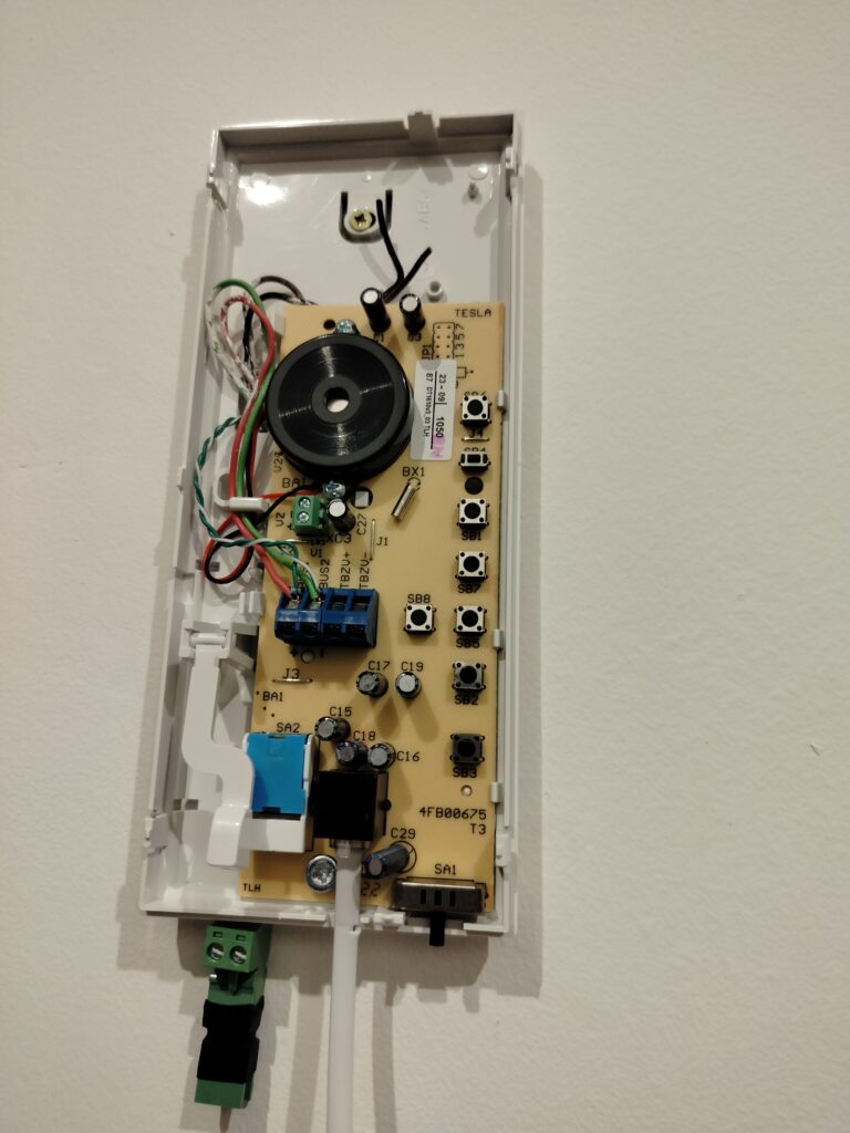
I wanted to be notified when someone rings when we are not at home so I decided to reverse engineer it.
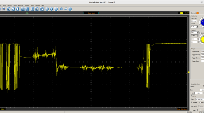
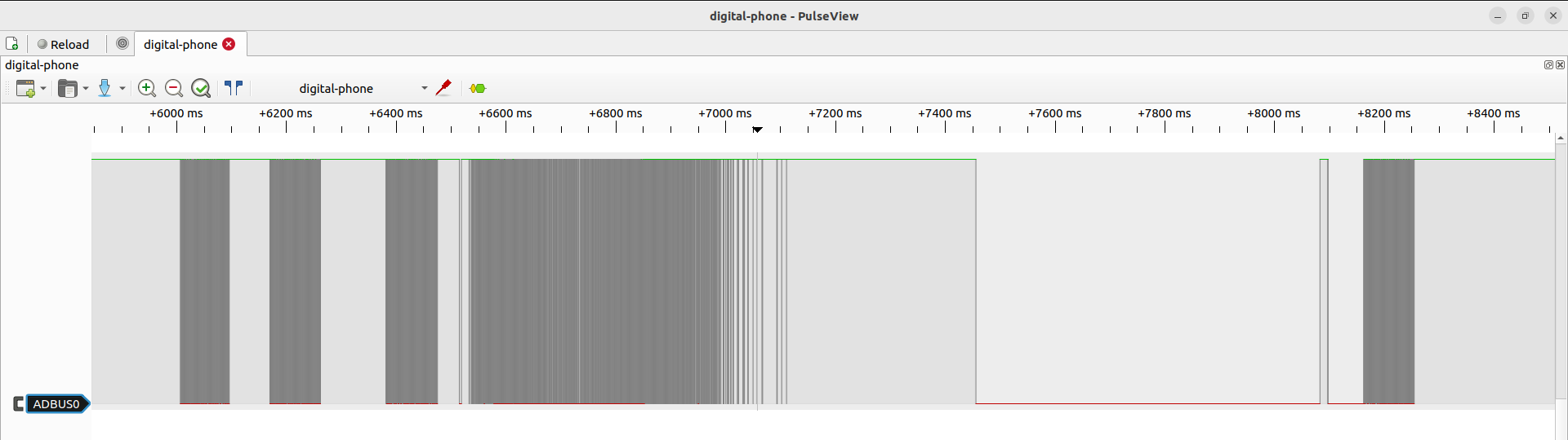
During idle, there is a voltage of about 23V which is there to power the phones as they don’t have any other power supply; during a call, the voltage drops to about 12,6V and current goes to 47mA. So I took my scope and started to measure the signal. In short, I have found, that there is some sort of digital signal and analog voice modulated on top of the DC component (timeframe of one call):
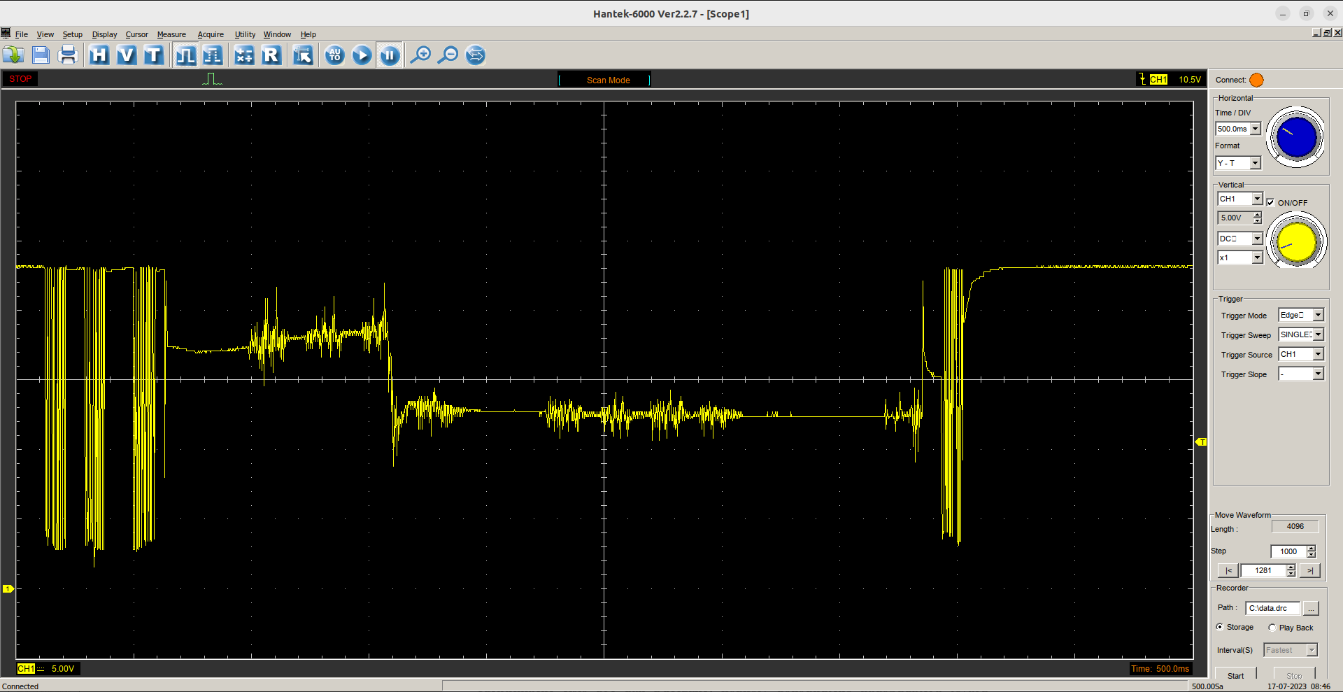
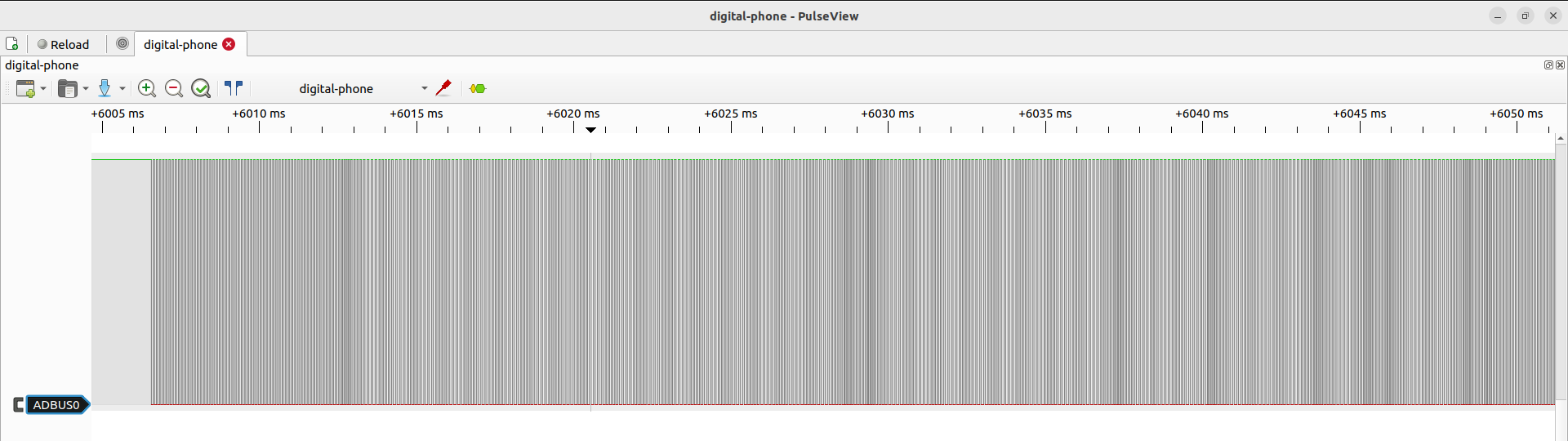
On first sight, it didn’t remind me of any common line encoding and my scope has a short buffer so I decided to convert it to logic levels and use a logic analyzer.
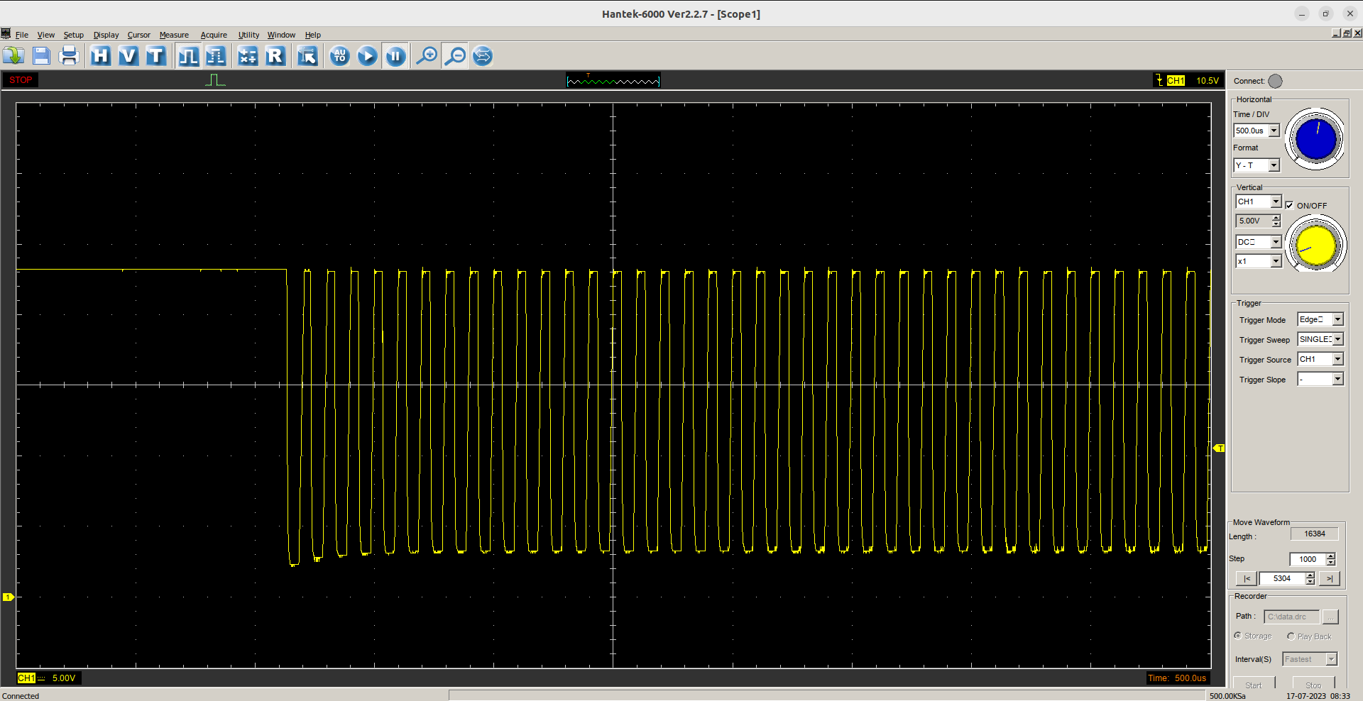
It also didn’t make more sense but then I played with zoom and suddenly saw it there:
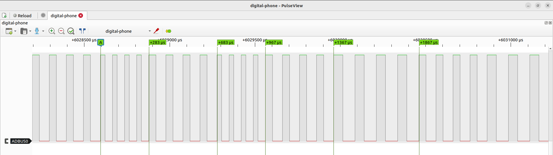
The data is encoded using symbols consisting of 4 PWM pulses. There are 3 symbols – logical 0, logical 1 and stuffing (‘-‘). Each frame starts with several dozens of stuffing symbols. Then bit symbols are sent each one followed by one stuffing symbol. On the picture above, “A” marks the start of 1 then follows: -, 1, -, 0, -, 0, … Each frame consists of 48 bits where the last 8 bits are checksum. They are being sent in MSB first order. The checksum is computed using this formula.
Once I got the frames decoded, it was just a matter of watching the communication. I managed to decode following structure:
| dst address (16b) | src address (16b) | command (8b) | checksum (8b) |
Addressing
Some facts from installation manual:
– each phone has assigned “system number” (SN) in range 000-999
– only numbers 000-323 can be called from another phone (due to addressing scheme)
– there can be one “main phone” (MP) and up to 3 “secondary phones” (SP) for each SN
– there can be up to 8 “electronic gatekeepers” (GK)
– each phone has it’s own “intercom number” (IN) which can be computed like this:
IN1 = ((SN x 4 + X) / 216) + 1
IN2 = (((SN x 4 + X)mod 216) / 36) + 1
IN3 = (((SN x 4 + X)mod 36) / 6) + 1
IN4 = ((SN x 4 + X)mod 6) + 1
where X = 0 for MP and 1-3 for SP
Considering these facts, I was able to decode the address format:
000GSSSSSSSSSSXX – 16bits
– G – is_gk – if address belongs to GK it equals 0
– S – system number for MP/SP, zeroes for GK
– X – number of MP/SP or number of GK
Commands
There is 1 byte space for commands so theoretically there can be 256 commands. I was able to decode these ones.
The call from GK always starts with “ping” to check if the called MP exists, MP needs to respond with OK. Then GK sends “call_from_eg” and the MP starts ringing. When an user picks up, MP sends “accepted_call_from_eg”, GK responds with OK and voice communication is established. The you can also see open_lock and hangup commands with pretty clear meaning. Here is the whole communication between MP with SN 7 and GK 1:
src:{sn:0 mn:1 is_gk:1} dst:{sn:7 mn:0 is_gk:0} cmd:ping(64) cs:147
src:{sn:7 mn:0 is_gk:0} dst:{sn:0 mn:1 is_gk:1} cmd:OK(0) cs:211
src:{sn:0 mn:1 is_gk:1} dst:{sn:7 mn:0 is_gk:0} cmd:call_from_eg(10) cs:201
src:{sn:7 mn:0 is_gk:0} dst:{sn:0 mn:1 is_gk:1} cmd:OK(0) cs:211
…
src:{sn:7 mn:0 is_gk:0} dst:{sn:0 mn:1 is_gk:1} cmd:accepted_call_from_eg(12) cs:199
src:{sn:0 mn:1 is_gk:1} dst:{sn:7 mn:0 is_gk:0} cmd:OK(0) cs:211
…
src:{sn:7 mn:0 is_gk:0} dst:{sn:0 mn:1 is_gk:1} cmd:open_lock(14) cs:197
src:{sn:0 mn:1 is_gk:1} dst:{sn:7 mn:0 is_gk:0} cmd:OK(0) cs:211
…
src:{sn:7 mn:0 is_gk:0} dst:{sn:0 mn:1 is_gk:1} cmd:hangup_from_eg(16) cs:195
src:{sn:0 mn:1 is_gk:1} dst:{sn:7 mn:0 is_gk:0} cmd:OK(0) cs:211
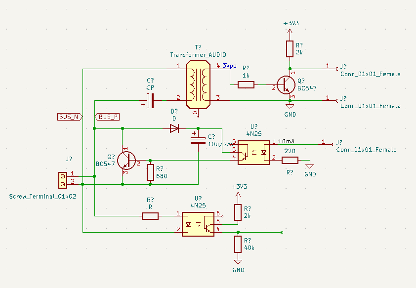
Hardware
I have used a transformer to isolate my device from the bus. The middle section is simple and is used for transmit. For receive, I was first using the bottom part but then I replaced it with the transistor behind the transformer. Audio is sent/received from pins 3,4 on the transformer.
Audio signal goes to integrated soundcard on OrangePI, digital signal from transistor is received by STM32F1, the pulse widths are measured and sent via virtual serial port over USB. The software then checks the pulse widths and counts and decodes into bits and frames. The transmit path also goes via the virtual COM, but it is sent as full frames and line encoded on the MCU. When the software detects incoming call to specified MP, it will start a SIP call to defined number in PSTN and the call can be normally answered, you can talk or open lock using DTMF.
You can find the complete software on https://github.com/danielkucera/tesla-2bus – there is both the control software and firmware for the STM32.
This project is still a work in progress, I am thinking about implementing it completely in an MCU and make the calls using SIM800 GSM module and power everything from the bus.
Feel free to ask in the comments if you have any questions.
Hello danman, any progress on that please? This is exactly what i was looking for.
Hi Lubos,
what exactly would you like to see?
Hello, thanks for your reply. My MP comes also with analogue video signal (it is present only when communication is present, but i can deal with that by jumpwiring video bus in GK because i have access to GK in our house, so i already have digitalized video signal and need working audio). My goal is to integrate Tesla 2BUS with Loxone smart home. I am currently ordering parts based on your schematic from Aliexpress to give it a try. Does the audiotransformer have some specs (eg 8ohm). Also I have RPI4 instead of OrrangePi, assuming that would not be a problem. Thank you.
Hi,
it was this one: https://a.aliexpress.com/_EuNI1ZR
I am not saying it is perfect but it does the job.
I can send you a pair for the shipping costs, if you like, just send me your info using contact form.
One note – I am not sure if Rpi4 has analog audio input/output – but you should be able to use some cheap USB soundcard.
Thank you, i ordered everything. First of all i will try without orangepi and audio (reading bus only)… i suppose i can connect STM directly to PC a try to read BUS using python lib you wrote…
Yes, that should work. I was also thinking about porting to RP2040 but then I lost interest. Please let me know about your progress once you have something.
Hey Dan,
good job!
I was wondering, what would be the easiest approach if I want to only unlock the gate using let’s say ESP32? Would something like that be possible?
Thanks
Ahoj David,
that should be doable, yes.
I did not finish the esp32 implementation because I didn’t want to bother with audio handling and without it, it didn’t make sense to me.
I think, I was having issues with interrupt speed to measure the pulse lengths.
Maybe using rp2040 with PIO would be a better solution but with some tricks esp32 could work too.
Hi Dan,
great job! Congrats.
I would like to open the door from remote. As I know the Tesla Stropkov a ring from the door station and a phone pick up is required before I can activate to door open.
Did you find a way to open the door from remote?
Ahoj Marcel,
if you mean, that you want to open the door without anyone needing to ring you first, that is possible.
If you check the original manual, it is possible to call the gatekeeper from your doorphone and then open the door.
So using my code, you can create a random unused doorphone number, initiate a call to gatekeeper and send the signal for opening.
Hi Danman, ok great. I will try 🙂 thank you
Hello Dan and Marcel!
In our system at home i was able to notice this as available command outside the call
{“ts”: 1769026440.192932, “src”: 1143, “dst”: 1112, “cmd”: 129, “cmd_name”: “force_trigger_doorlock”}
phone simply shoots this and if ok gate replies with ack.
Hope this helps 🙂
Hi Lubos,
that’s nice. Thanks for sharing.