Hi all,
this post will be about my homemade IoT thermostat. 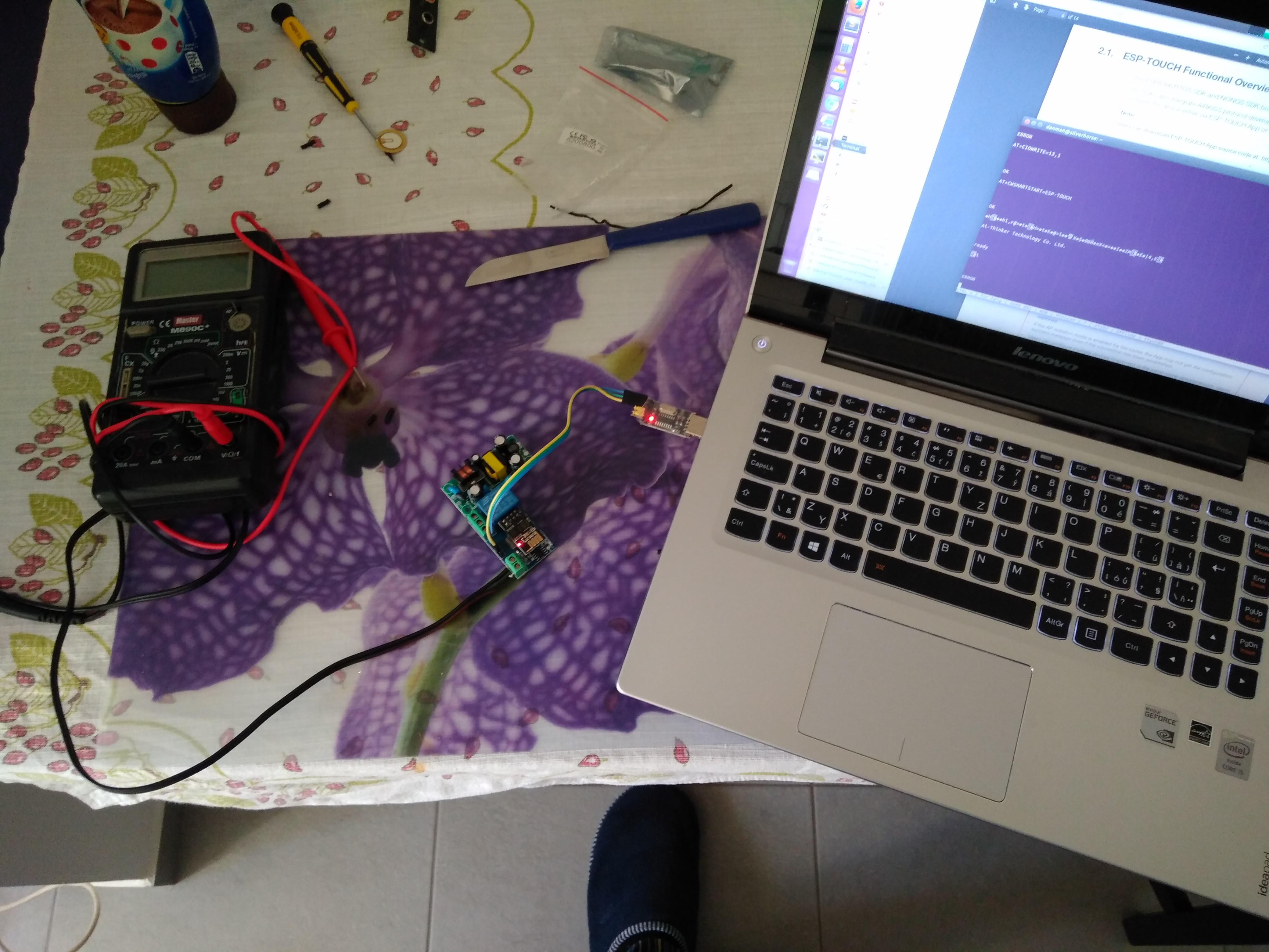 The goal was to not install any cables (because I live in a rented flat), to go really cheap and to be able to set the temperature from anywhere. I’ll also give you some tips you should think about when building your own. Let’s get started.
Original solution
The original solution consisted of a commercial programmable thermostat by local brand “meibes” (which was badly suited near door and we also put a wardrobe in front of it)  and a central heating unit with regulation valve.
 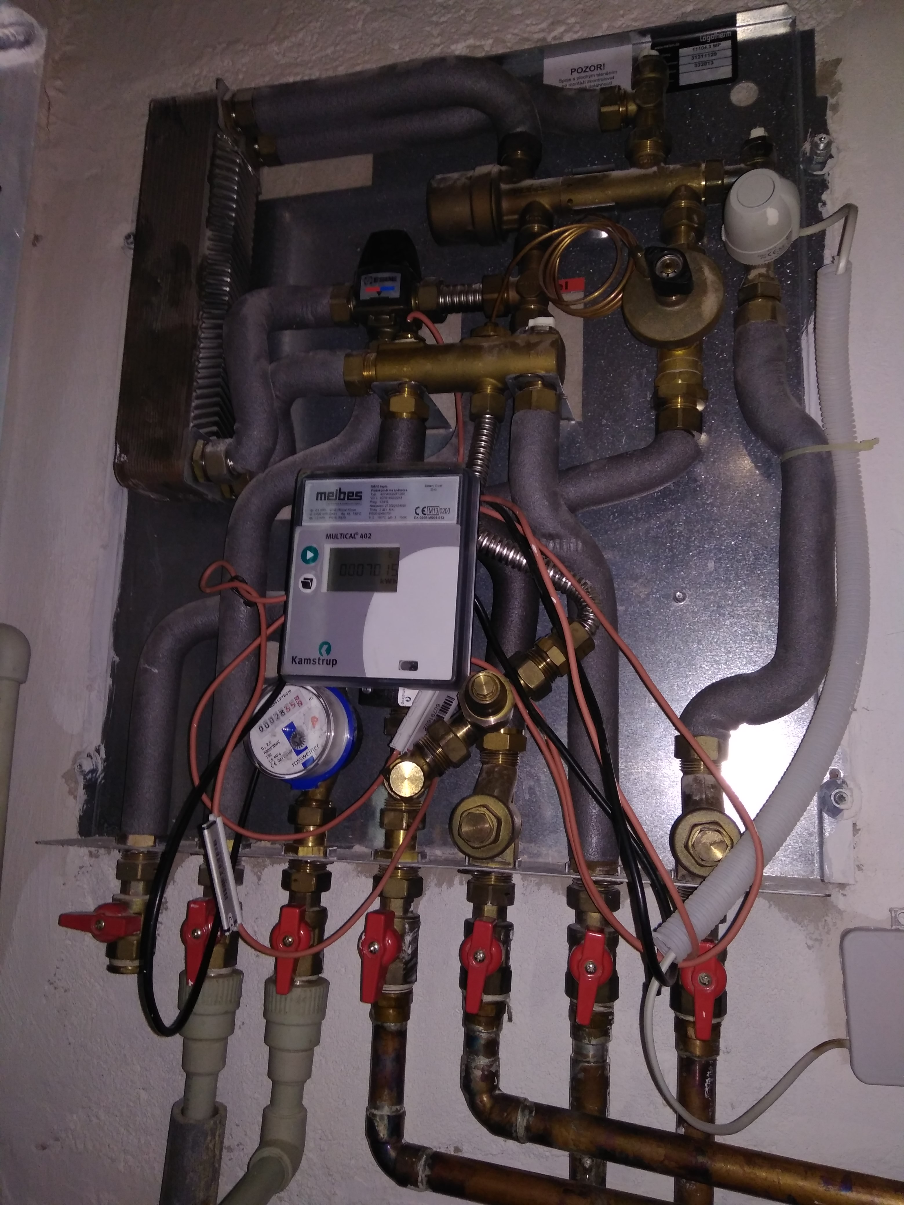 On the picture you can see a few pipes:
- the rightmost two are my central heating circuit with white electronic actuator on top of a regulation valve which opens and closes the heating circuit
- middle two are a heat distribution circuit for the whole house
- second from the left is cold water input
- and the leftmost connected pipe is hot water output for kitchen and bathroom
It took me few minutes to fully understand the system but at the end of the day it’s not that complicated. There is a heat exchanger up left, mixing valve for hot water, heat meter, regulation valve with actuator and a few other things.
My main point of interest was the electric actuator (datasheet). It is controlled by 230V AC input. When it is powered, it takes a few minutes to fully open and it also takes a few minutes to close after the power is turned off. It is connected in following box. White cable goes to actuator, one black is mains inlet and the other black goes to original thermostat.

My idea
The main idea was to not install any cables between the thermometer unit and the actuator control unit so I split it into 2 autonomous blocks communicating over netwprk:
- thermometer unit with webui
- wifi enabled relay
Wifi enabled relay
After some search on my favorite e-shop I found this unit. It contains greatly customizable esp8266 module (which means I should be able to hack it so it will work as I need) and a relay capable of switching AC mains. I just needed to add 5V power supply module which I had “on stock”. When the WiFi module arrived, I started to experiment with it. After power-up, standard AT command firmware was present.
Ai-Thinker Technology Co. Ltd.


ready

WIFI CONNECTED

WIFI GOT IP

AT+GMR


AT version:1.2.0.0(Jul  1 2016 20:04:45)

SDK version:1.5.4.1(39cb9a32)

Ai-Thinker Technology Co. Ltd.

Dec  2 2016 14:21:26

OK
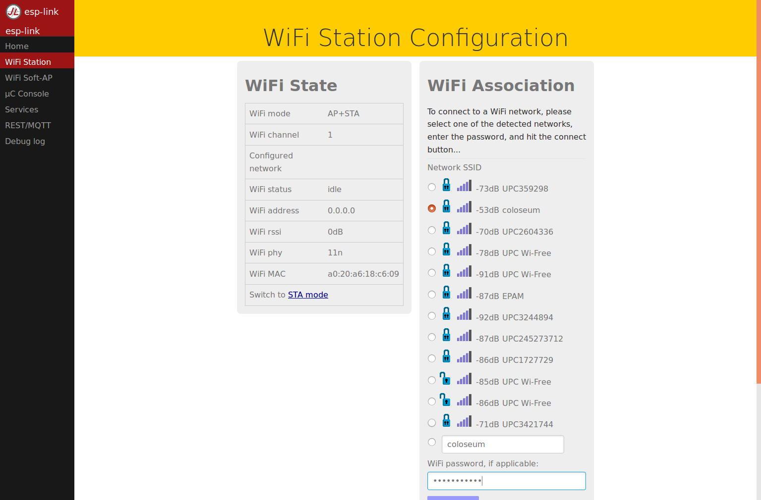
The item description page was saying, that every time after boot you need to initialize it so it connects to WiFi an listens on some TCP port. This was not an acceptable solution for me so I started googling for some alternative firmwares. The easiest solution was to upload esp-link firmware which looked nice.
With this, I was able to send commands directly via UART to attached controller STC15F104. This is where my problems started. After some serious googling, I wasn’t able to find a working control sequence to switch the relay. Although I found some documentation for the module, nothing worked. Nor the seller responded to my question. So I thought that I might skip talking to STC15F104 and try to directly control the relay via pin on esp.
esp-link can’t do this, so I found another firmware which I don’t need to compile: NodeMCU (there is a web service which will do this for you). My basic condition was that the relay must open if anything screws up (module doesn’t boot, wifi disconnects, power outage, etc.). When I connected GPIO0 or GPIO2 to relay (of course via onboard transistor), the module refused to boot because these pins also control the boot sequence. So I chose different pin which is not HI by default – RXD.
 I simply removed a resistor between STC and switch transistor, soldered a wire and connected it to TXD pin on esp. This way the relay was still open after power-up without needing to toggle-off the pin by software.
Next thing was the esp control program. With a condition: “switch off when something goes wrong” I ended up with something like this:
init.lua:
-- Global Variables (Modify for your network)
ssid = "****"
pass = "****"

-- Configure Wireless Internet
print('\nAll About Circuits init.lua\n')
wifi.setmode(wifi.STATION)
print('set mode=STATION (mode='..wifi.getmode()..')\n')
print('MAC Address: ',wifi.sta.getmac())
print('Chip ID: ',node.chipid())
print('Heap Size: ',node.heap(),'\n')
-- wifi config start
wifi.sta.config(ssid,pass)
wifi.sta.autoconnect(1)
-- wifi config end

-- Run the main file
dofile("telnet.lua")
dofile("main.lua")
main.lua:
sv = net.createServer(net.TCP, 30)

val = gpio.LOW

mytimer = tmr.create()
mytimer:register(240000, tmr.ALARM_SEMI,
function()
  node.restart()
end)

mytimer:start()

function receiver(sck, data)
  mytimer:stop()
  mytimer:start()
  gpio.mode(9, gpio.OUTPUT)
  if data:sub(1,1) == "1" then
    val = gpio.HIGH
  else
    val = gpio.LOW
  end
  gpio.write(9, val)
end

if sv then
  sv:listen(3333, function(conn)
    conn:on("receive", receiver)
    conn:send(val)
  end)
end
telnet.lua from here
After boot, it connects to WiFi, starts telnet interface for debugging on 2323/TCP and starts the main program. Main.lua simply listens on 3333/TCP and responds with current relay state. After receiving ‘1’ it switches the relay on, otherwise it switches it off. It also resets watchdog timer which reboots the unit after few minutes without received command – this causes wifi reconnect and relay switchoff.
Installation
I just connected my unit to the original connect box like you can see on these pictures:


 Problems
Stuck original thermostat
First problem was, when I woke up at 1 am feeling that I sleep in a backing oven 😀
 I needed to get up and turn the heating off. I found out that the problem was caused by original thermostat which I left in the circuit parallel to my relay. Evening before I have had removed a battery from it. Since then it was switching the circuit randomly on and off the delay on actuator caused that it was still on. So I disconnected the original thermostat from the circuit.
Stuck esp
Next problem was when esp disconnected from wifi.
It happed when I didn’t have implemented a restart timer so the esp disconnected and kept relay switched on. Solved by that autorestart timer.
Burned transistor
Even before putting the relay into circuit, I tested it by sending a fast stream of zeroes and ones to the relay. First it was clicking and blinking nicely but then it stopped and stayed on permanently. After a short investigation, I found out that the switching transistor is burnt and thus still conducting. Probably the relay killed it because of a voltage spike. So I replaced it with BC817 and also added 1N4148 directly on relay pins.
After these issues it works reliably so far.
WebUI with thermometer
The thermometer unit consists of OrangePI (which is also my media center – behind monitor) and TemPer USB in my livingroom.

It was quite easy to make the thermometer work: I just downloaded and installed this python utility. It’s output is ideal for next processing:
# apt install git python-usb python-setuptools
# git clone https://github.com/smeek/temper-python
# cd temper-python/
# python setup.py install
# temper-poll -c
24.1
I didn’t want to write the webui from scratch so I googled for similar project and found this:
https://www.variantweb.net/blog/building-a-thermostat-with-the-raspberry-pi/
https://github.com/sjenning/rpi-thermostat
I just edited the main program and web page and the result is here.
https://github.com/danielkucera/rpi-thermostat
It’s a Go daemon with measuring loop and webserver. It loads a configuration on startup and periodically checks for room temperature. If it reaches upper or lower trigger, it changes its internal relay state which is periodically sent to my wifi relay unit. Even if the state doesn’t change, it writes it to the relay to keep it from automatic restart. Both upper and lower trigger can be changed via web. After changing, all settings are saved into config file.

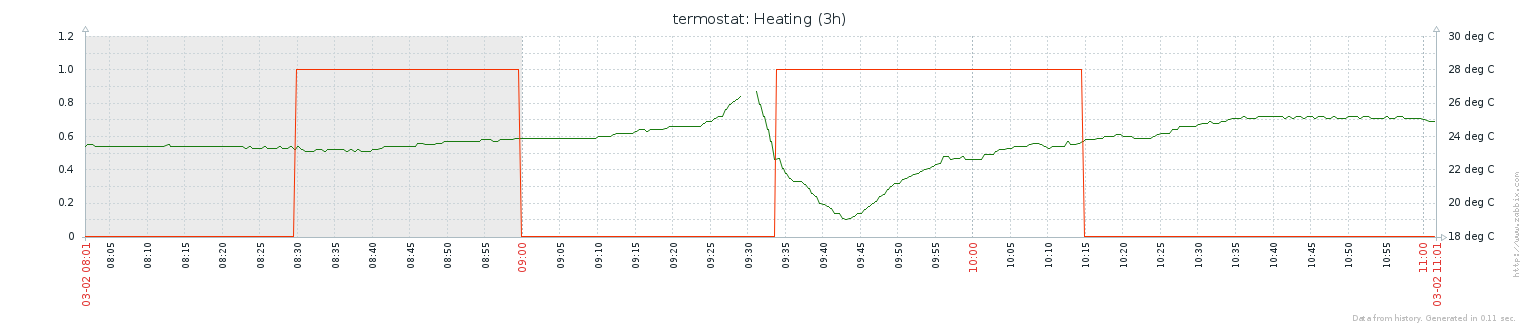
It provodes data for browser in form of a JSON. So I also created two items in my zabbix which periodically checks for their values (see pictures in problem sections)
Problems
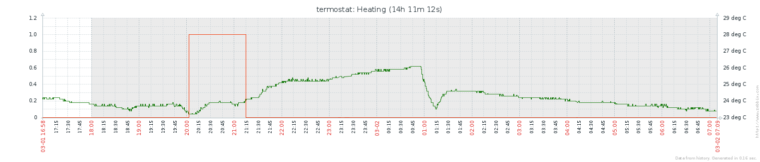
The only problem I had from begining were very strange measured temperature values. The change was very lazy whether the heating was on or a window was open.
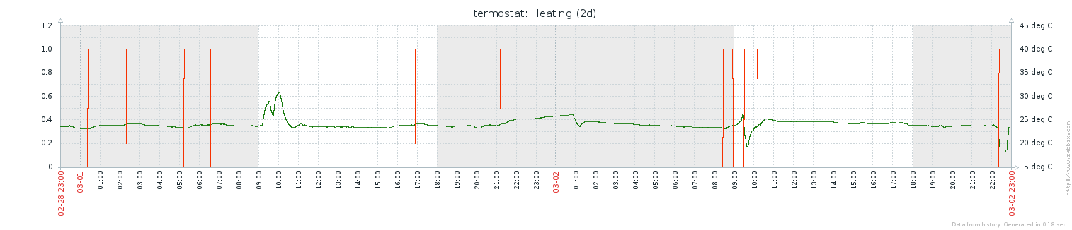 Then I made one change: moved the sensor from under the white table to height about 1,5m above floor. This changed measured values dramatically:
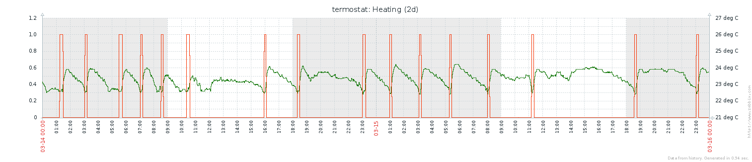 Since then the thermostat unit works without any problem. The calibration of the sensor is a little bit off but it’s not a big deal. I set the temperature according to my personal feeling.
tl;dr tips:
- Don’t reinvent the wheel: get inspired by a similar project
- Put the sensor in height (about 1,5m)
- Create some watchdog for unexpected problems
- Test everything
- Use some kind of monitoring to debug your system
So far I am very satisfied with the build and its stability and want to thank to Seth for inspiration and for publishing original rpi-thermostat code.
Looking forward for your comments.
Bye!