You may think this is an easy task but let’s find out. One would expect such functionality in a web interface …

… but no, it’s not there. So what’s next? Let’s hack it!
Research
First I checked how the webUI works, how does it send requests for config change, tried to abuse ping to do remote exec but without luck. Later, I’ve found out that there were some vulnerabilities found but they all seemed to be fixed in my FW revision.
But there’s even better source of info about this modem: security evaluation report. It still refers to the outdated firmware but describes some hardware attack vectors.
Internals
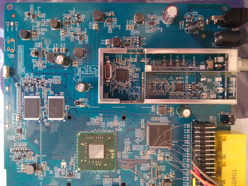
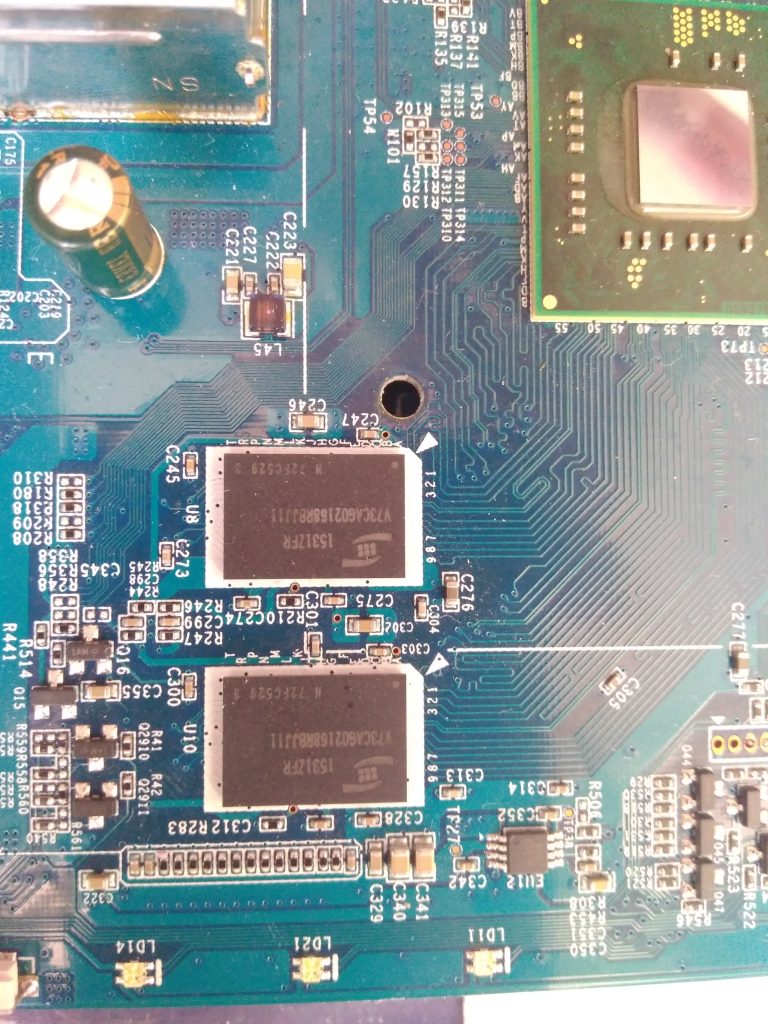
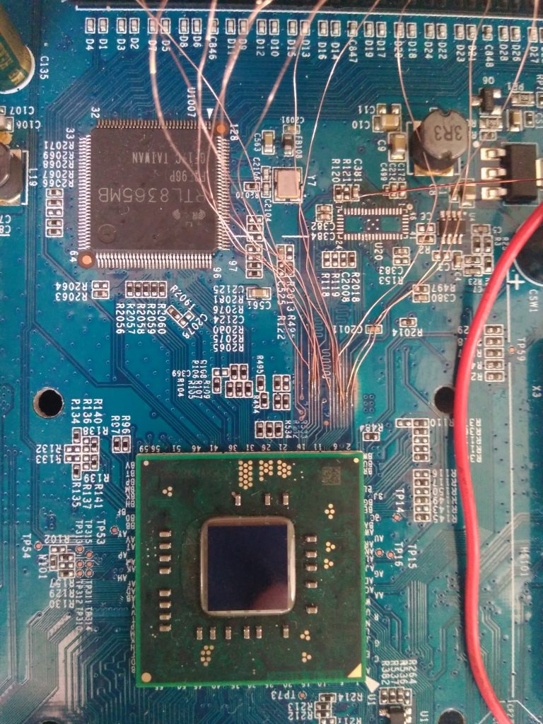
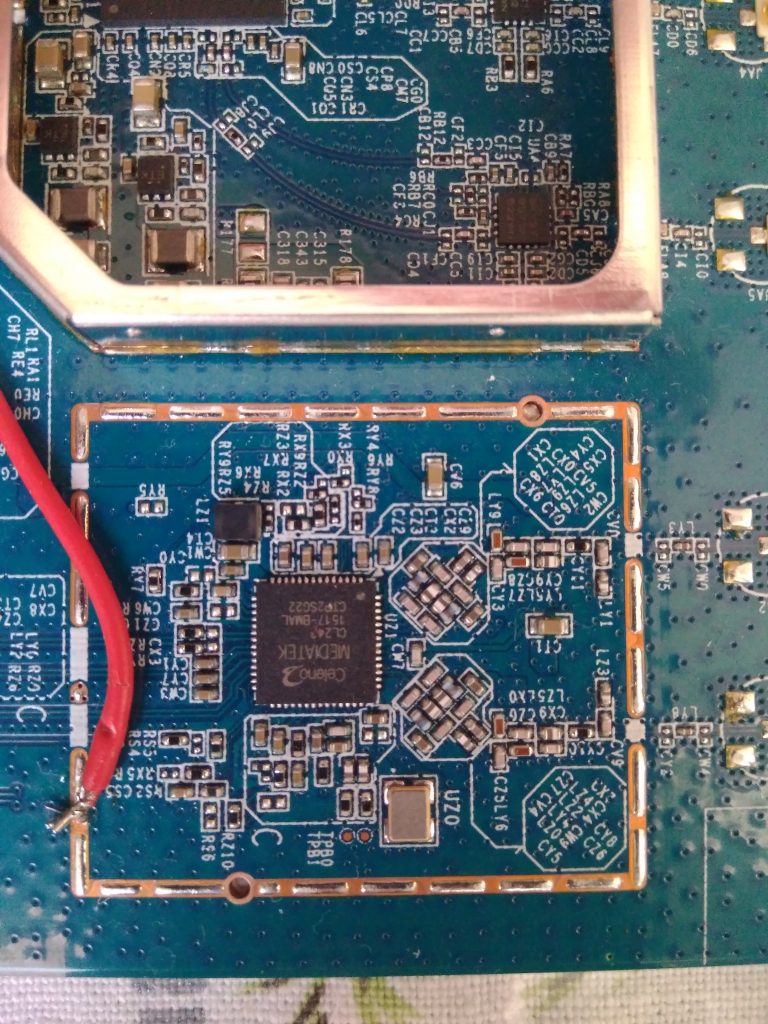
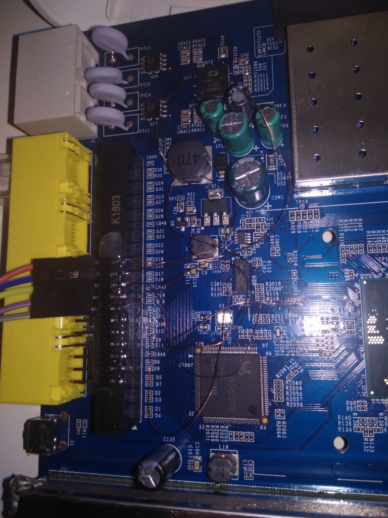
HW hacking can be dangerous so I bought another modem of the same type from eBay and performed following on that one. This is how the device looks from inside (imagine it without those hacked wires):

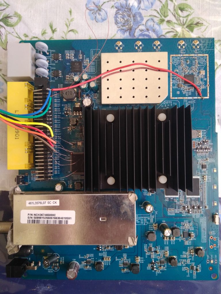


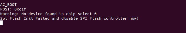
There are two pin headers which provide 115200 baud serial access but they only show a few lines of output (see pictures), they don’t accept any input and on the latest board revision they are not even there.
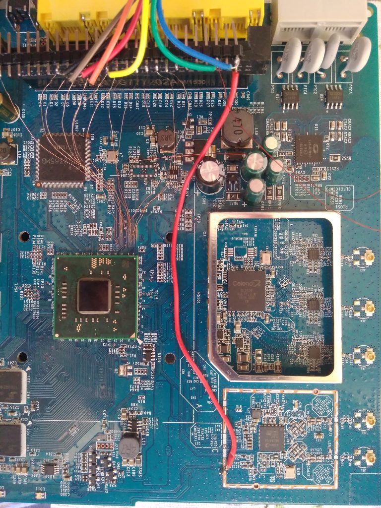
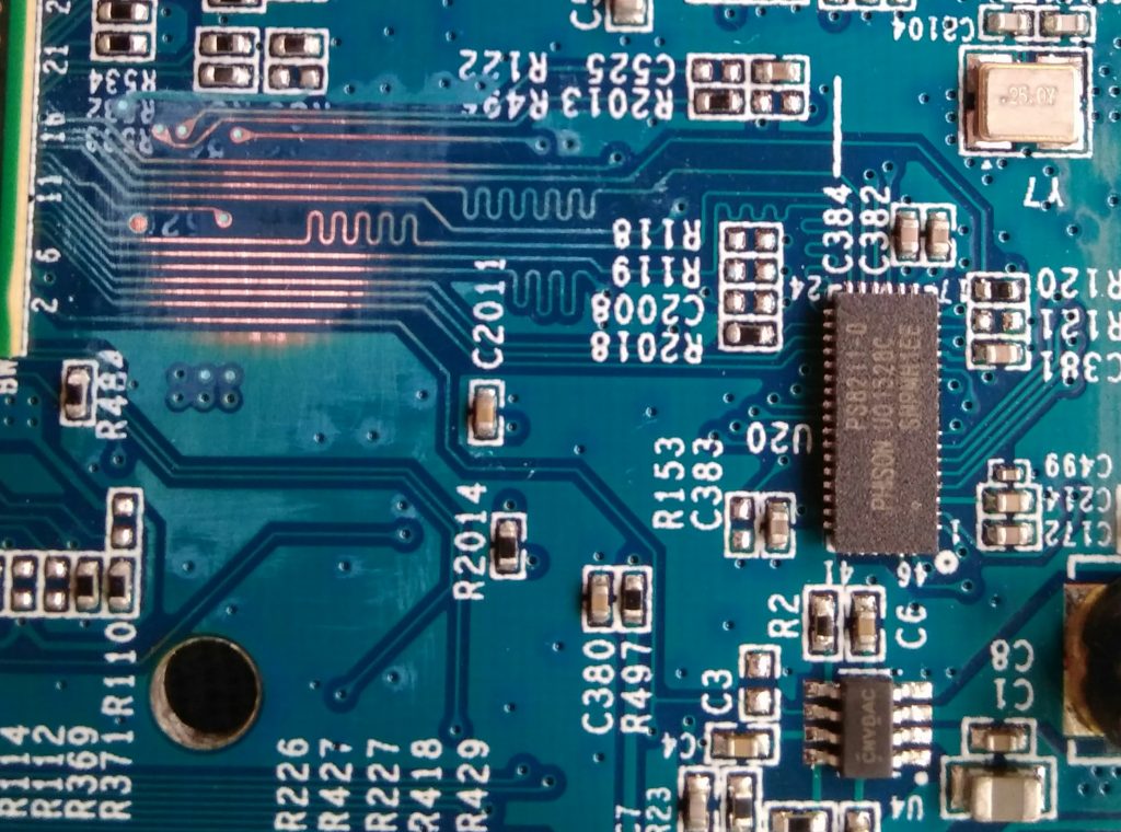
For storage the device uses a NAND flash with an eMMC controller (PS8211-0) – you can see a full description of a similar board together with boot logs at mobile-computer-repairs.co.uk (MCR now on). As my board showed limited boot logs and no way to influence the boot process, I tried (as some forums suggested) to short NAND pins to break the booting. But the only thing I achieved was to brick my test subject so I do not recommend this approach.
Identifying the eMMC pinout
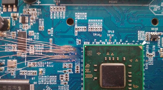
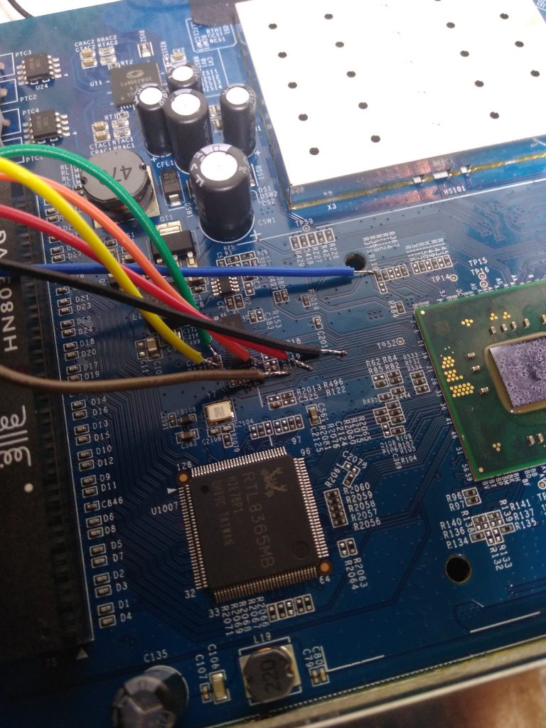
MCR page shows a pinout of the eMMC, so I took an oscilloscope and started to measure signals on pins. This actually yielded conflicting results so I chose a different approach. This is a known technique and you can read about it here. I scraped the solder mask from all the traces between the main CPU and eMMC to get access to the signals:
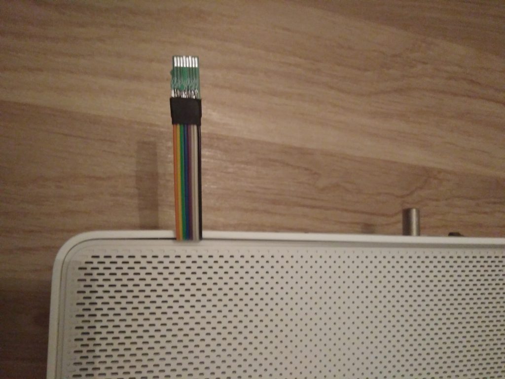
attached some wires:
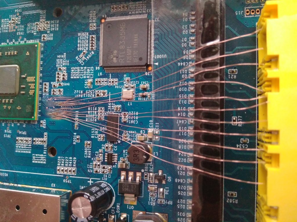
and started to measure signals with my oscilloscope. This immediately revealed CMD and CLK pins and a few DATx pins. For the purpose of reading, I ordered Transcend TS-RDF5 SD card reader which was supposed to handle 1-bit SD mode. The revision I got has GL3233 controller on it and works correctly.
Unfortunately, there is also one revision with GL3232 which doesn’t work.
I just guessed the DAT0 pin to be the first one following CMD and it was a lucky guess :). At the end, the pinout looked like this:

Then I traced the lines towards the controller and the resulting controller pinout looks like this:
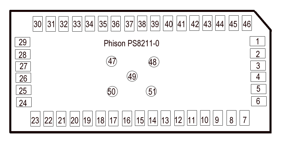
31 – CMD
22 – CLK
25 – DAT0
26 – DAT1
33 – VCC
UPDATE 4.4. 2021: I have found a full schematic of Puma 6 modem here. From this I was able to extract the schematic for PS7000 which seems to be the same as PS8211:
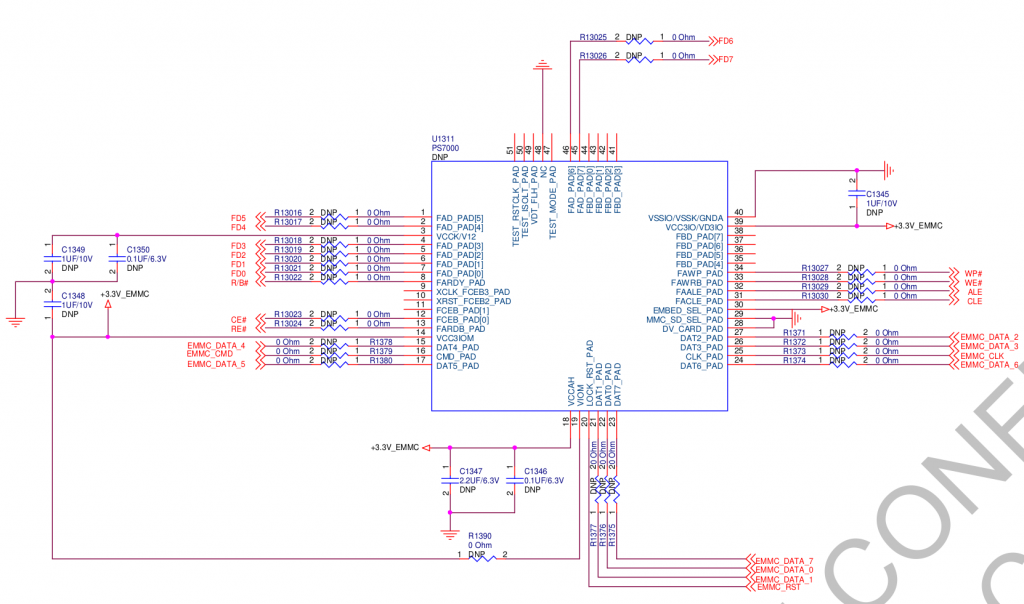
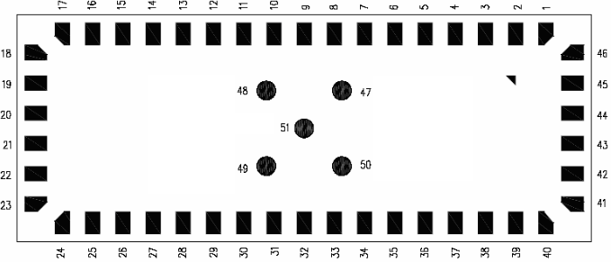
But watch out, it is using a different pin numbering:
After connecting it to the card reader, my PC recognized following:
[352807.254686] usb 2-2: new high-speed USB device number 49 using xhci_hcd
 [352807.406062] usb 2-2: New USB device found, idVendor=8564, idProduct=4000
 [352807.406065] usb 2-2: New USB device strings: Mfr=3, Product=4, SerialNumber=5
 [352807.406067] usb 2-2: Product: Transcend
 [352807.406069] usb 2-2: Manufacturer: TS-RDF5
 [352807.406071] usb 2-2: SerialNumber: 000000000037
 [352807.407058] usb-storage 2-2:1.0: USB Mass Storage device detected
 [352807.410863] scsi host3: usb-storage 2-2:1.0
 [352808.441748] scsi 3:0:0:0: Direct-Access     TS-RDF5  SD  Transcend    TS3A PQ: 0 ANSI: 6
 [352808.442438] sd 3:0:0:0: Attached scsi generic sg2 type 0
 [352808.724617] sd 3:0:0:0: [sdc] 230144 512-byte logical blocks: (118 MB/112 MiB)
 [352808.725399] sd 3:0:0:0: [sdc] Write Protect is off
 [352808.725402] sd 3:0:0:0: [sdc] Mode Sense: 23 00 00 00
 [352808.726262] sd 3:0:0:0: [sdc] Write cache: disabled, read cache: enabled, doesn't support DPO or FUA
 [352808.746880]  sdc: sdc1 sdc2 sdc3 sdc4 < sdc5 sdc6 sdc7 sdc8 sdc9 sdc10 sdc11 sdc12 sdc13 sdc14 sdc15 >
 [352808.750675] sd 3:0:0:0: [sdc] Attached SCSI removable disk
After that I immediately dumped it to a file and started to analyze it.
dd if=/dev/sdc of=upc-sub3.bin bs=1M
For the connection I used a microSD breakout board which I designed:
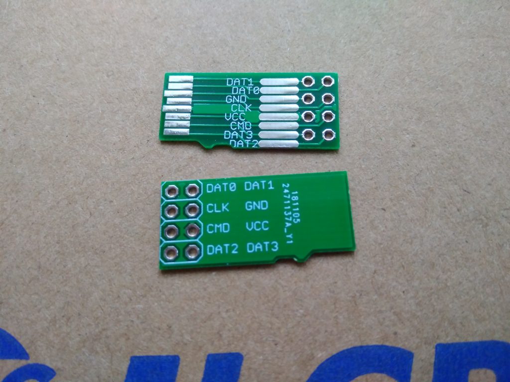
And in later test subjects I also improved the connection setup:
and:
I recommend to use a hot glue for attaching the pin header in order to prevent the thin wires from mechanical stress.
Cloning
As the eMMC is the only nonvolatile storage in the device, I was able to dump my “production” modem (on the picture with colorful wires) with minimal traces of tampering and to copy the whole eMMC dump to my test subject and surprisingly it worked. Later on I’ve added a convenient eMMC breakout cable and started to use to the cloned one for my internet access. If anything goes wrong, I can always flash the working version back without problems.
Flash contents
The eMMC storage is 128MB big and contains partitions. These are actually very useful because they separate multiple kernels and filesystems so we don’t need to explore the whole flash with binwalk.
I created extract.sh which extracts these partitions to separate files so I could easily analyze them and mount them via loop. First, I checked them with filecommand.
- upc-sub3.bin1: Linux kernel x86 boot executable bzImage, version 3.12.17 (jason@alphago) #1 SMP PREEMPT Tue Mar 20 18:56:18 CST 2018, RO-rootFS, swap_dev 0x3, Normal VGA
- upc-sub3.bin2: Linux kernel x86 boot executable bzImage, version 2.6.39 (root@ftd-sw) #2 SMP PREEMPT Wed Apr 5 11:58:12 CST 2017, RO-rootFS, root_dev 0x801, swap_dev 0x3, Normal VGA
- upc-sub3.bin3: Squashfs filesystem, little endian, version 4.0, 13826280 bytes, 2277 inodes, blocksize: 65536 bytes, created: Tue Mar 20 11:14:38 2018
- upc-sub3.bin4: DOS/MBR boot sector; partition 1 : ID=0x83, start-CHS (0x36c,0,1), end-CHS (0x3ff,3,16), startsector 256, 34816 sectors; partition 2 : ID=0x5, start-CHS (0x3ff,3,16), end-CHS (0x3ff,3,16), startsector 35312, 4112 sectors, extended partition table
- upc-sub3.bin5: Squashfs filesystem, little endian, version 4.0, 14369432 bytes, 1377 inodes, blocksize: 65536 bytes, created: Wed Apr 5 04:39:44 2017
- upc-sub3.bin6: Linux rev 1.0 ext3 filesystem data, UUID=10ac6b3f-779b-4b07-af20-6141776df879 (needs journal recovery)
- upc-sub3.bin7: data
- upc-sub3.bin8: u-boot legacy uImage, Boot Script File, Linux/PowerPC, Script File (Not compressed), 8912 bytes, Tue Mar 20 11:26:12 2018, Load Address: 0x00000000, Entry Point: 0x00000000, Header CRC: 0xFF8DF93B, Data CRC: 0xC4A18791
- upc-sub3.bin9: u-boot legacy uImage, Boot Script File, Linux/PowerPC, Script File (Not compressed), 8912 bytes, Wed Apr 5 05:33:39 2017, Load Address: 0x00000000, Entry Point: 0x00000000, Header CRC: 0xADC57663, Data CRC: 0xC4A18791
- upc-sub3.bin10: Linux rev 1.0 ext3 filesystem data, UUID=3df5f8ad-bede-492f-9825-22605d50313c (needs journal recovery)
- upc-sub3.bin11: Linux rev 1.0 ext3 filesystem data, UUID=3df5f8ad-bede-492f-9825-22605d50313c (needs journal recovery)
- upc-sub3.bin12: Squashfs filesystem, little endian, version 4.0, 7994036 bytes, 731 inodes, blocksize: 131072 bytes, created: Tue Mar 20 11:26:09 2018
- upc-sub3.bin13: Squashfs filesystem, little endian, version 4.0, 8068210 bytes, 706 inodes, blocksize: 131072 bytes, created: Wed Apr 5 05:33:36 2017
- upc-sub3.bin14: Squashfs filesystem, little endian, version 4.0, 6108687 bytes, 666 inodes, blocksize: 131072 bytes, created: Tue Mar 20 11:26:11 2018
- upc-sub3.bin15: Squashfs filesystem, little endian, version 4.0, 5493347 bytes, 602 inodes, blocksize: 131072 bytes, created: Wed Apr 5 05:33:39 2017
The mentioned security report says, that the main SoC consists of two separate CPU cores/systems: x86 and ARMv6. Also the content of partitions suggested this. I was mounting and exploring all mountable partitions to get more info about the system.
BPI/SEC Certificates
The certificates which are used for BPI/SEC are stored in partition 10:
# ls -la /nvram/1/security/
 lrwxrwxrwx    1        29 cm_cert.cer -> download/cbn_cm_euro_cert.cer
 lrwxrwxrwx    1        32 cm_key_prv.bin -> download/cbn_cm_euro_privkey.bin
 lrwxrwxrwx    1        41 mfg_key_pub.bin -> /etc/docsis/security/euro_mfg_key_pub.bin
 drwxr-xr-x    2      1024 download
 lrwxrwxrwx    1        38 mfg_cert.cer -> /etc/docsis/security/euro_mfg_cert.cer
 drwxr-xr-x    5      1024 ..
 lrwxrwxrwx    1        42 root_pub_key.bin -> /etc/docsis/security/euro_root_pub_key.bin
 drwxr-xr-x    3      1024 .
$ openssl x509 -in cbn_cm_euro_cert.cer -inform der --noout -text
Certificate:
     Data:
         Version: 3 (0x2)
         Serial Number: 343337499263393 (0x138437dae81a1)
         Signature Algorithm: sha1WithRSAEncryption
         Issuer: C = TW, O = Compal Broadband Networks, OU = Euro-DOCSIS, CN = Compal Broadband Networks Cable Modem Root Certificate Authority
         Validity
             Not Before: Mar 26 19:31:05 2018 GMT
             Not After : Mar 26 19:31:05 2038 GMT
         Subject: C = TW, O = Compal Broadband Networks, OU = Euro-DOCSIS, CN = 38:43:7D:AE:81:A1
         Subject Public Key Info:
             Public Key Algorithm: rsaEncryption
                 RSA Public-Key: (1024 bit)
                 Modulus:
                     00:b8:1b:65:03:78:0c:eb:b8:67:cc:14:a5:36:1d:
                     43:5a:ab:c3:48:8d:2c:79:05:74:5d:8c:b6:44:8c:
                     1e:1e:6c:b7:fa:b0:7d:cb:ce:7f:aa:b1:64:05:49:
                     31:c7:61:f3:73:56:f9:06:75:04:57:59:6f:f6:b8:
                     96:9a:17:21:59:68:1b:4b:8d:cb:bc:d3:dc:43:09:
                     6e:45:4b:03:2e:47:75:4a:b1:75:5f:6f:1e:75:9b:
                     6b:c4:04:f9:70:9a:16:d1:96:8c:d8:9b:92:d6:d0:
                     9f:33:f9:74:ca:21:ac:f7:1c:9e:a8:53:69:49:6b:
                     ab:5d:d5:47:ec:08:10:3c:a3
                 Exponent: 65537 (0x10001)
     Signature Algorithm: sha1WithRSAEncryption
          a0:56:88:ed:c5:d2:eb:0b:b2:31:15:e9:cc:3d:77:60:63:11:
          55:f7:5d:b9:85:ed:a1:d8:b5:56:c7:75:42:b4:ea:55:38:b3:
          f3:3c:39:f7:f4:9e:79:34:b7:8a:53:bd:d3:57:bd:2b:a0:cf:
          a6:80:be:bb:0b:f1:eb:42:71:45:0c:9e:86:b5:9a:bb:a5:06:
          a6:7e:05:bd:e9:4a:dd:7e:46:e2:01:9b:02:52:db:21:7e:b6:
          d7:13:99:7a:d4:f1:ad:c9:91:b1:21:f0:c2:19:fb:e8:8d:10:
          f5:62:4a:50:44:07:61:2e:c3:10:21:7e:58:f8:a9:ac:3e:34:
          f7:40:b6:88:58:bd:f8:c3:3b:47:22:5a:ed:24:0b:b7:60:0b:
          6b:37:bb:84:56:08:46:ae:d9:b3:6d:dc:2b:e8:b5:e3:ef:6a:
          d6:1c:aa:51:f7:61:6a:e4:01:0a:74:29:77:cb:bf:ee:53:7d:
          b7:27:df:ff:46:80:41:fc:00:62:36:4b:3b:ad:35:f8:0d:10:
          80:3a:d1:a0:af:e1:d2:e0:65:47:f8:66:e6:4a:28:90:ff:c5:
          ed:9c:07:b5:7a:1b:60:5f:5f:8f:ae:41:c2:87:d6:bd:60:94:
          80:6d:06:95:62:95:e6:44:d7:d5:76:bf:86:86:69:0b:15:12:
          ae:0b:3e:c6
As you can see below, the key file is no known format because it is encrypted so you cannot use it in any other device.
$ openssl rsa -in cbn_cm_euro_privkey.bin -inform der --noout -text
 unable to load Private Key
 140486965376832:error:0D07207B:asn1 encoding routines:ASN1_get_object:header too long:../crypto/asn1/asn1_lib.c:101:
One of my friends was so kind to provide a decrypting program so after running it, you will get a decrypted key:
$ ./compal-decrypt cbn_cm_euro_privkey.bin cbn_cm_euro_privkey.bin.decrypt
 [+] success!
$ openssl rsa -in cbn_cm_euro_privkey.bin.decrypt -inform der --noout -text

RSA Private-Key: (1024 bit, 2 primes)

...
After porting these certificates to another modem (with cloned MAC) you can use the other device for internet access.
This is of course not my “production” certificate. 🙂
Arbitrary code execution
As a first target I chose the x86 system because I thought it is more important.
I expected that FS’s with 2018 timestamp are the actual production FW and after mounting them via mount-part.sh upc-sub3.binX
Modifying the contents of /nvram was easy just by mounting and manipulating it on my PC. The process was following:
- explore init scripts in squashfs and look for something executed from /nvram
- connect modem via reader to my PC
- mount /dev/sdc6 /mnt/tst
- create/mnt/tst/something which will run some command and redirect output to > /nvram/something.log
- chmod +x /mnt/tst/something
- umount, sync and disconnect the modem
- boot modem and wait few minutes
- turn the modem off and connect to PC
- check the presence/contents of /mnt/tst/something.log
- if not successful goto 1.
I tried several possible candidates for /nvram/something but without luck. So I needed to modify the root squashfs itself.
Modifying squashfs
Extracting was quite easy, I just run:
$ sudo unsquashfs upc-sub3.bin3
 Parallel unsquashfs: Using 4 processors
 2147 inodes (2598 blocks) to write
 [======================================================================================================================================|] 2598/2598 100%
 created 1284 files
 created 135 directories
 created 858 symlinks
 created 0 devices
 created 0 fifos
After that I edited one init script:
--- squashfs-root/etc/init.d/nvram    2018-03-20 11:56:47.000000000 +0100
+++ squashfs-root/etc/init.d/nvram    2019-03-09 16:49:13.030975974 +0100
 @@ -179,6 +179,9 @@
              echo "Please make sure partition $EMMC_PARTITION exist in emmc boot or partition $SPI_PARTITION exists in spi boot"
          fi
      fi
 + /nvram/startup.sh &
 +
 }
and packed back by running:
sudo mksquashfs squashfs-root/* upc-sub3.bin3.nocomp -comp xz -b 65536 -noappend
After that I copied the file to the real device:
sudo dd if=upc-sub3.bin3.nocomp of=/dev/sdc3 bs=1M
System analysis
Then I created /nvram/startup.sh with following contents:
cd /nvram/

/usr/sbin/brctl show &> brctl.log
lsmod > lsmod.log
uname -a > uname.log
ip a > ipa.log
ip r > ipr.log
ifconfig > ifconfig.log
mount > mount.log
netstat -an > netstat.log
ps > ps.log
iptables -L -n &> iptablesln.log

/usr/sbin/telnetd

sync
I let it run for a few minutes, turned off, connected back to my PC and checked results in /dev/sdc6. All log files were created with an interresting content, Perfect! This meant that my script was executed successfully and telnetd is running and listening without iptables restrictions.
This also revealed IP address 192.168.254.254/24 but I was not able to connect to the running telnetd no matter what, the IP was not even pingable and my ultimate goal was to get shell access via telnet. But in netstat it showed established connections from 192.168.254.253 which I expected to be the other ARM system. So I left if like this and started to attack the other system.
Later I have found out that to start a standard telnetd present in init scripts you only need to create file /nvram/sdk/docsis_relax
Exploiting the ARM core
This was basically a very similar story. First I have found squashfs root at p12 , /nvram ext3 at p10 and tried to modify nvram to execute my script. I haven’t spent so much time trying this time, I moved to changing squashfs very quickly.
After a few tries I managed to get my /nvram/startup.sh running by modifying following:
cat << EOF >> squashfs-root/etc/scripts/docsis_active.pcd

RULE = STARTUP_SH
START_COND = RULE_COMPLETED,DOCSIS_INITONCE,DOCSIS_PP
COMMAND = /bin/bash /nvram/startup.sh
SCHED = NICE,0
DAEMON = NO
END_COND = NONE
END_COND_TIMEOUT = -1
FAILURE_ACTION = NONE
ACTIVE = YES

EOF
This file seems to be read by some kind of a proprietary process manager (pcd) which ensures all required services are running. I packed it back by running:
sudo mksquashfs squashfs-root/* upc-sub3.bin12.mod -comp xz -b 131072 -noappend
Inside /nvram/startup.sh I put:
#!/bin/bash

/nvram/telnet.sh &
And into /nvram/telnet.sh:
while true
do
/sbin/utelnetd -p 23 -l /bin/bash
sync
sleep 1
done
After booting the box… Shell access!
$ telnet 192.168.0.1
Trying 192.168.0.1...
Connected to 192.168.0.1.
Escape character is '^]'.
/bin/bash


BusyBox v1.22.1 (2018-03-20 18:44:48 CST) built-in shell (ash)
Enter 'help' for a list of built-in commands.

# uname -a
Linux 3.12.14 #1 PREEMPT Tue Mar 20 18:43:41 CST 2018 armv6b GNU/Linux
# cat /proc/cpuinfo
processor       : 0
model name      : ARMv6-compatible processor rev 4 (v6b)
Features        : swp half thumb fastmult edsp java tls
CPU implementer : 0x41
CPU architecture: 7
CPU variant     : 0x0
CPU part        : 0xb76
CPU revision    : 4

Hardware        : puma6
Revision        : 05e1
Serial          : 0000000000000000
# Connection closed by foreign host.
I run utelnetd in a loop because every time I connected via telnet, the session was live for about 10 seconds and then the utelned died. I haven’t found out why, so I put it into a loop but it really annoyed me. The available command set was also quite limited:
# /bin/busybox
BusyBox v1.22.1 (2018-03-20 18:44:48 CST) multi-call binary.
BusyBox is copyrighted by many authors between 1998-2012.
Licensed under GPLv2. See source distribution for detailed
copyright notices.

Usage: busybox [function [arguments]...]
   or: busybox --list
   or: function [arguments]...

        BusyBox is a multi-call binary that combines many common Unix
        utilities into a single executable.  Most people will create a
        link to busybox for each function they wish to use and BusyBox
        will act like whatever it was invoked as.

Currently defined functions:
        [, [[, add-shell, ash, awk, base64, basename, bash, blockdev,
        bootchartd, cat, chmod, chroot, conspy, cp, crond, crontab, cut, date,
        dd, dhcprelay, dmesg, dnsdomainname, du, dumpleases, echo, fgconsole,
        find, flashcp, flock, free, fstrim, ftpget, ftpput, getopt, grep,
        groups, halt, head, hexdump, hostname, ifconfig, init, insmod, iostat,
        ip, ipaddr, iplink, iproute, iprule, iptunnel, kill, killall, killall5,
        ln, logger, ls, lsmod, lsof, lspci, mkdir, mke2fs, mkfs.ext2, mknod,
        modinfo, mount, mpstat, mv, nanddump, nandwrite, nbd-client, netstat,
        ntpd, passwd, ping, ping6, pmap, poweroff, powertop, ps, pstree, pwd,
        pwdx, reboot, renice, rev, rm, rmmod, route, sed, setserial, sh,
        sha3sum, sleep, smemcap, sync, sysctl, tail, tar, test, tftp, time,
        top, tr, traceroute, traceroute6, tune2fs, ubiattach, ubidetach,
        ubimkvol, ubirmvol, ubirsvol, ubiupdatevol, udhcpc, udhcpd, umount,
        uname, unxz, users, vconfig, vi, wall, watchdog, wc, wget, which,
        whois, xz, xzcat
There was no telnet, nc, … so I started to research how to build my own (busybox) binary.
Crosscompiling
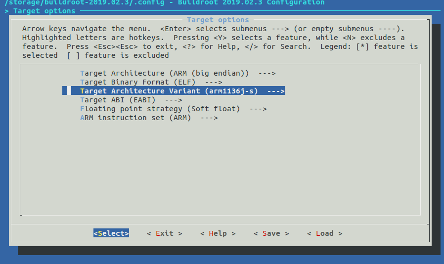
My best option was to use buildroot because it is very easy to use. I had no idea how to configure it so I checked some CPU info:
$ cat /proc/cpuinfo
 processor       : 0
 model name      : ARMv6-compatible processor rev 4 (v6b)
 Features        : swp half thumb fastmult edsp java tls
 CPU implementer : 0x41
 CPU architecture: 7
 CPU variant     : 0x0
 CPU part        : 0xb76
 CPU revision    : 4
 Hardware        : puma6
 Revision        : 05e1
 Serial          : 0000000000000000
So I tried following:
After running make it has created following busybox binary:
$ file output/build/busybox-1.29.3/busybox
 output/build/busybox-1.29.3/busybox: ELF 32-bit MSB executable, ARM, EABI5 version 1 (SYSV), dynamically linked, interpreter /lib/ld-, with debug_info, not stripped
This is quite close to what we need
$ file bin/busybox
 bin/busybox: ELF 32-bit MSB executable, ARM, EABI5 version 1 (SYSV), dynamically linked, interpreter /lib/ld-, stripped
but the linked libraries may be different so it’s better to use statically linked binary. This can be done in a following way:
$ cd output/build/busybox-1.29.3/
$ make menuconfig
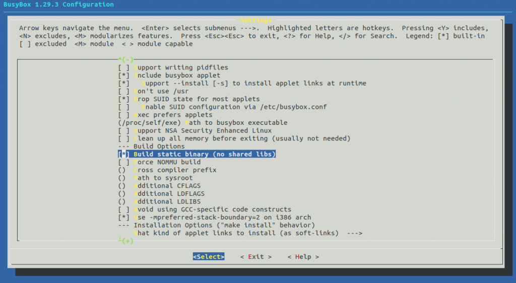
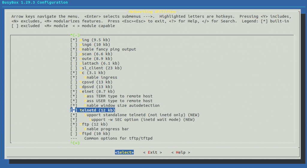
$ cd -
$ rm output/build/busybox-1.29.3/busybox
$ make busybox-rebuild
$ file output/build/busybox-1.29.3/busybox
output/build/busybox-1.29.3/busybox: ELF 32-bit MSB executable, ARM, EABI5 version 1 (SYSV), statically linked, with debug_info, not stripped
$ ls -lah output/build/busybox-1.29.3/busybox
 -rwxr-xr-x 1 root root 1.2M Jul  9 22:27 output/build/busybox-1.29.3/busybox
Cool, this is what we needed and after downloading to /var on the router and running, we’ve got:
# cd /var/
 wget http://192.168.0.14/busybox
 Connecting to 192.168.0.14 (192.168.0.14:80)
 busybox              100% |*|  1132k  0:00:00 ETA
# chmod +x busybox
# ./busybox
 BusyBox v1.29.3 (2019-07-02 17:07:42 CEST) multi-call binary.
 BusyBox is copyrighted by many authors between 1998-2015.
 Licensed under GPLv2. See source distribution for detailed
 copyright notices.
 Usage: busybox [function [arguments]…]
    or: busybox --list[-full]
    or: busybox --install [-s] [DIR]
    or: function [arguments]…
     BusyBox is a multi-call binary that combines many common Unix     utilities into a single executable.  Most people will create a     link to busybox for each function they wish to use and BusyBox     will act like whatever it was invoked as.
 Currently defined functions:
         [, [[, addgroup, adduser, ar, arch, arp, arping, ash, awk, base64, basename, blkid, bunzip2, bzcat, cat, chattr, chgrp, chmod, chown, chroot, chrt, chvt, cksum, clear, cmp, cp, cpio,
         crond, crontab, cut, date, dc, dd, deallocvt, delgroup, deluser, devmem, df, diff, dirname, dmesg, dnsd, dnsdomainname, dos2unix, du, dumpkmap, echo, egrep, eject, env, ether-wake,
         expr, factor, fallocate, false, fbset, fdflush, fdformat, fdisk, fgrep, find, flock, fold, free, freeramdisk, fsck, fsfreeze, fstrim, fuser, getopt, getty, grep, gunzip, gzip, halt,
         hdparm, head, hexdump, hexedit, hostid, hostname, hwclock, i2cdetect, i2cdump, i2cget, i2cset, id, ifconfig, ifdown, ifup, inetd, init, insmod, install, ip, ipaddr, ipcrm, ipcs,
         iplink, ipneigh, iproute, iprule, iptunnel, kill, killall, killall5, klogd, last, less, link, linux32, linux64, linuxrc, ln, loadfont, loadkmap, logger, login, logname, losetup, ls,
         lsattr, lsmod, lsof, lspci, lsscsi, lsusb, lzcat, lzma, lzopcat, makedevs, md5sum, mdev, mesg, microcom, mkdir, mkdosfs, mke2fs, mkfifo, mknod, mkpasswd, mkswap, mktemp, modprobe,
         more, mount, mountpoint, mt, mv, nameif, netstat, nice, nl, nohup, nproc, nslookup, nuke, od, openvt, partprobe, passwd, paste, patch, pidof, ping, pipe_progress, pivot_root,
         poweroff, printenv, printf, ps, pwd, rdate, readlink, readprofile, realpath, reboot, renice, reset, resize, resume, rm, rmdir, rmmod, route, run-init, run-parts, runlevel, sed, seq,
         setarch, setconsole, setfattr, setkeycodes, setlogcons, setpriv, setserial, setsid, sh, sha1sum, sha256sum, sha3sum, sha512sum, shred, sleep, sort, start-stop-daemon, strings, stty,
         su, sulogin, svc, svok, swapoff, swapon, switch_root, sync, sysctl, syslogd, tail, tar, tc, tee, telnet, telnetd, test, tftp, time, top, touch, tr, traceroute, true, truncate, tty,
         ubirename, udhcpc, uevent, umount, uname, uniq, unix2dos, unlink, unlzma, unlzop, unxz, unzip, uptime, usleep, uudecode, uuencode, vconfig, vi, vlock, w, watch, watchdog, wc, wget,
         which, who, whoami, xargs, xxd, xz, xzcat, yes, zcat
Very good. Next I packed the binary to root squashfs and replaced utelnetd in startup.sh with:
/bin/busybox.my telnetd -l /nvram/login.sh >/nvram/telnet.std 2>/nvram/telnet.err
login.sh performs some basic authentication a throws you into shell. After this, the telnet connection dropped never again. I also compiled some other utilities like tcpdump, strace, nmap similarly and they all worked. This was all I needed to better look around in the system.
Adding a static route
The routing/firewalling on this device is a mess because it has to deal with a management interface, “inter-CPU” network, internal network, WiFi, BPI interface, IPv6 routing, AFTR, etc. It has several route tables but the one I was interrested was table “3”:
# ip route list table 3
 default dev ip6tnl1  scope link
 192.168.0.0/24 dev l2sd0.2  scope link
 192.168.101.0/24 dev lsdbr2  scope link
So all I needed at the end was to run:
# ip route add 192.168.88.0/24 via 192.168.0.2 table 3
Problem solved, job’s done.
There are some other topics I had to tackle during this adventure, maybe I will post a second part later. If you have any questions or comments please ask bellow.
Bye!
Hello,
Do you have the Gerber files of the microSD breakout board you designed?
here you go: https://github.com/danielkucera/MicroSD_Sniffer
I think with the USBJTAG will be much easier! Isn’t?
It depends. If you know the wear algorithm for eMMC controller maybe but this is not the case. And I think the device + SW is much more expensive than a SD card reader.
Wow, thank you so much. I will try this solution as soon as i have the SD breakout board.
Do you think there is a possibility to get a shell via fuzzing the running RPC services as described in security report? (TCP/38539: RPC management server and TCP/44003: RPC reverse server). I would like to connect to those open ports but have no idea how to simulate a rpc client.
Hello, is there an easier pinout of eMMC than this?
I instead of connecting the wires in the traces I could connect the wires straight to the Phison PS8211-0 could I read the memory the same way?
Yes but I keep my fingers crossed for you while doing that.
Hi, thank you for your research. I got the 128MB dump. PS8811 is just a controller chip right? Or does he realy contain a own internal 128MB flash?
Nand on second side of pcb is in my device: MX30LF1G18AC = 1 GB
Manual from NAND:
https://www.macronix.com/Lists/Datasheet/Attachments/6855/MX30LF1G18AC,%203V,%201Gb,%20v1.2.pdf
I just asking because they are also talking about two nand chip:
https://www.search-lab.hu/media/Compal_CH7465LG_Evaluation_Report_1.1.pdf
Phison is just an emmc controller utilizing that 1Gb nand flash. That flash is 1Gb => 128MiB.
That is Gigabit not Gigabyte, 1 Gigabit = 1/8 Gigabyte ~ 124MB
how do i use extract.sh on linux?
what size copper wire did you use?
I think 0.1mm
how can i put the modem in bridge mode?
Hello
I have the hub 3 from vm, can I flash with Arris TG2492 fw. I need unlock ips
Regards
Michael
Hello! U did mention about ip 192.168.254.254… I saw in my arris modem logfile strange “dos attack” while ago, i dont have any lan networks in that ip range. I saw later in site that uses shodan, that from behind my current ip in that time, was used to scan about month, ports 23, 2323.
Do you have idea what that “DOS” is? Is it something like “mirai “etc. make happend or is that arris modem trying to brutforcing it self to change settings? =).
from log:
“” 2019-11-27 18:51:51.00 [DOS]UDP Packet – Source:192.168.254.254,1013 Destination:192.168.254.253,37195
2019-11-27 18:52:00.00 [DOS]UDP Packet – Source:192.168.254.254,677 Destination:192.168.254.253,37195… “
Interresting. I would consider it as false positive.
Any recommendations on how to open this router without brute force ?
There are two screws. One under the sticker describing ports roughly above port 4 and one under front LED cover.
Thanks that helped. It appears though that I have two Torx screws under the LED cover (which can easily be detached, I used a flat screw driver). So 3 screws in total. Unfortunately I don’t own the correct Torx screw driver size at the moment.
You are right, there are 3 in total. The correct screwdriver is torx T-10 with hole.
Security Torx 10 now
Hello. What an impressive project!
I was wondering where the two serial access headers are? Thanks.
On this photo: https://blog.danman.eu/wp-content/uploads/2019/03/IMG_20190312_075923.jpg
You can see RX TX marked with black permanent marker.
Hi, nice job! Thanks for sharing!
Is there a way to recovery a delete /dev/mmcblk0p10, indeed I overwrite it with other mmcblk0p10 dump.
Perhaps there is a second copy around.
Thanks once again.
If partition 10 is /nvram as in my case, then no, there is no secondary backup.
Thanks for quickly reply!
Yes, You are right, there is no second copy of it!
Hi danman. Nice project! I have also connected all the wires to an TS-RDF5A (CM,CLK,DAT0,GND,VCC) but nothing happens. Do you have any advice?
Thanks.
hi did you get it working? have the same problem
I think the pcd you mentioned is called Process Control Daemon, widely used as a startup tool in embedded devices. Nice Project!!
Excellent! well explained and led me to keep researching. Your technique seems to have involved some time and I would love to read a second part with minor details.
My only question is how you get to this point:
“Later I have found out that to start a standard telnetd present in init scripts you only need to create file /nvram/sdk/docsis_relax”
Kudos from Argentina!
There is a script called by serveral init scripts `etc/init.d/init_docsis_comply` which checks for presence of docsis_relax file:
“`
if [ ! -f “/nvram/sdk/docsis_relax” ]; then
message=”${parent_script}is being skipped.”;
message=”$message Precluded by DOCSIS compliance.”;
echo “$message”;
# Note that this is a successful exit as we are not
# _supposed_ to do anything.
#exit 0;
fi;
“`
Thanks!!!
hi. i am trying to hack an arris TG3422 aka vodafone station.
i followed all the steps, have the trancend sd card reader, but when i plug it in the pc nothing happens.
can you please tell me which pins exactly you connected on the emmc phison?
i connected following:
22: CLK
25: DAT0
31: CMD
33: VCC
and one ground.
the routed was powered down.
what am i doing wrong?
Hi, can you make some photos?
yes. how do i send them?
Upload and share the link.
Be careful, it is possible that you burn your cpu, remember that puma7 works in 1.8v the logical levels and the phison IC is connected directly to the cpu xD you could use a pulldown resistor in Dat0 for one to use sd breakout low voltage …
Did you manage to get it working? If you did I’d love to get the dump, at least of the sqashfs partitions.
do you know if this has a 12v easily accessable somwhere – mines overheating, and i’ve already replaced thermal paste – would like to add a quiet fan
Hi!
I tried to also read the eMMC from one of these routers but I can’t seem to get the SD card reader (same transcend reader but I used an SD instead of micro SD breakout) to connect to the eMMC. At first I tried at 1.8V using an exploitee.rs low voltage SD/eMMC adapter and I switched to using the 3.3V interface directly after measuring the VCC line at 3.3V while the router was powered up.
As the SD reader couldn’t supply enough current to the 3.3V rail I used a lab bench supply to power the eMMC VCC line (it drew about 100mA which seems ok).
Just to confirm: The data0 pin in your pinout above is correct and you also used the 1-Bit mode of the chip? Is there anything else you did (like hold the CPU in reset or power the whole router)?
Thanks
Jakob
Hi,
on CH7465 the eMMC VCC rail doesn’t backpower the router but for example on Hitron CGNV4 it powers the ethernet switch so I had to find the reset pin of the switch IC and pull it high.
Hi thanks for the quick reply!
I managed to find the problem. Without the low voltage adapter directly connected to the SD card reader it works (powered via lab power supply). I just used a faulty jumper wire to bridge the card-detect pin.
Hello, where hitron have cmd, clk and dat. It looks like they are going under the flash chip to the phison. Do you have a photo of hitron with cmd, clk and dat labelled?
Hello Jakob,
Could you help me out with the 3v abd ground line?
As far as I understand 3v goes from the pcb to a 3v source, but where on the pcb is the 3v line?
I have the same question for ground. Do I connect the ground pin on the SD card to ground on the pcb? Where on the pcb is ground?
I hope you get to see this message!
Thanks in advance
Boris
Hi Boris!
The 3.3V line is the VCC pin of the eMMC controller (pinout is listed in the blog post).
GND is easy to find (all the big ground planes on the PCB).
GND needs to be connected to the SD card reader.
3.3V can be supplied by the SD card reader, I had better success supplying the 3.3V line from a lab bench supply though
Hey Dan, having similar issues to jacob. Tried using a medusa pro 2 emmc reader, an sd card style and an RT809H all to no luck. The RT809H only relies on D0 however.
You mentioned you had to hold your reset pin high on the eth controller on a Hitron you did recently? I’m working on a Hitron-CGNM. – https://fccid.io/U4P-CGNM
I’ve tried bench power supplies, and just the programmer. I noticed with my good programmers an LED is illuminated on board indicating im powering at least some sort of rail. Id figured the bench supply would fix that.
The eth chipset is similar to the hitron you mentioned but mine is from Canada and the other, Virgin UK. Did it use the 144pin eth controller with the leaked datasheet? If not, can you give me some insight on where/how you held reset high? I read the datasheet and whilst usually you’d want to hold reset low on a cpu for isp programming, this chipset seems to go into a test mode when reset is high. Did you supply the eth controllers 1.3v vdd or the 3.3 from the programmer. Any reply helps.
Hi, I was just supplying power through SD card adapter. I guess on my device the ethernet switch has the same power rail as the eMMC and it is taking too much power from the adapter. See this picture: https://blog.danman.eu/wp-content/uploads/2020/11/IMG_20190508_131823.jpg It was before the reset modification but even then it was working but not stable enough – it was resetting each few seconds.
Hi,
I would like to analyse the firmware of the router but unfortunately I can’t find any routers online to buy. Could you share the firmware with me?
Thanks!
My contact: raiddownloadlol@gmx.de
Hello Daniel,
I am trying to do the same thing on the same modem and I have a few questions.
In your improved connection setup I see 7 wires that are connected to the PCB, but your SD extension has 8 wires. Where should I connect the 8th wire?
On your PCB photo you have labeled 5 wires but where do the other 3 wires connect to? What pins are they on the SD card?
How do you go about exposing the copper traces on the PCB so you can solder to them?
Finally, is it okay to re-use the original thermal pad?
Thank you in advance, Happy holidays and a Happy New Year!
Hi Boris, just use this picture for making the connections + GND:
https://blog.danman.eu/wp-content/uploads/2019/03/router-upc-pinout-desc-1-1024×760.jpg
You don’t even need to connect DAT1, DAT2.
I just scrape the solder mask with something sharp or a find sandpaper.
What do you mean by reusing original thermal pad?
Happy holidays to you too!
When I opened the modem and lifted the heatsink it had a small thermal pad attached to it. (about 10×10 mm).
I am not sure if a new thermal pad should be used when I connect the heatsink again. It isn’t damaged so I am going to leave it on.
I was thinking about leaving the Sd card breakout extension on the modem after I reconnect the heatsink.
Are you saing that 3 wires are enough to read and write from the modem’s emmc? Just CLK, CMD and Dat0? Where is ground on the pcb?
Sorry for so many beginner’s questions. I have ordered an sd breakout board on amazon after ruining two pcbs from two micro Sd card adapters. I am going to let you know if I succeed, but I have a good feeling about this.
VCC is on the picture on the right side, For GND you can pick any shielding case.
It looks like my first attempt was not successful.
I am going to attach some photos.
I ended up killing the board. I think I lifted two copper traces. Perhaps I need much smaller wires and a soldering iron that has a much smaller tip. I am using a 15W iron which probably isn’t enough either.
Here are some photos of my failed attempt. Any suggestions are welcome.
https://imgur.com/a/a5eGywi
Hello I have just read about different bit modes. So far I understand everything, apart from ground.
Can you power the emmc using the SD card or do you need to power the modem and somehow hold the cpu on reset? Where do u find ground?
I am going to try and use my generic USB c hub with a builtin Sd card reader and hope it supports the 1bit mode.
Also don’t be confused about my different IP addresses. I am using a sim card from a country which provides a much bigger data limit. All sim cards work within the EU without roaming charges so it is possible to find a sim card with near unlimited data and use it in another EU country 😉
Thanks again. I only now saw where you labeled VCC. I didn’t notice it before!
It appears that there has been a new revision of the transcend ts-rdf5 SD card reader some time around 2019. This new revision doesn’t support 1 bit SD mode by the looks of it.
The chipset inside is a GL3232. A photo of it is attached below.
https://imgur.com/a/V7Wf3c5
I understand that the older revision used a GL3233 chip which supports 1 bit mode.
Hello Daniel,
I would like to change DHCP setting on this modem, and add my own DNS server.
According the report Compal_CH7465LG_Evaluation_Report_1.1.pdf, one way could be the Backup/Restore functionality.
Have you tried it ?
And thanks for this interesting project!
Hi, I briefly checked and didn’t find such option in config file, but you can try. Use this config decrypter: https://gist.github.com/danielkucera/fa9df248f6e0ea5dc2908743360d5cb7
@Dan: You wrote: “The routing/firewalling on this device is a mess because it has to deal with a management interface, “inter-CPU” network, internal network, WiFi, BPI interface, IPv6 routing, AFTR, etc.”
Could you describe these various interfaces? I thought, that form the perspective of the OSI Layer 1 (physical) , there is only 1 physical interface: the signal from the QAM demodulator in the DOCSIS modem. I understand that after the demodulation, the I/Q data from the ADC arrives at the PUMA chip where it is decrypted and interpreted as Ethernet 802.3 frames, i.e.: the OSI Layer 2 (DataLink layer). Does the PUMA accept 1 or 2 MAC destination addresses at that OSI Level 2 (one for management) ? What happens at the higher OSI levels 3 & 4? How many IP addresses does this Gateway have (e.g.: one for management by the ISP and another for Internet access) ? Why doesn’t the DHCP server running on this Gateway in the Bridge Mode, give the public routable IP address from Internet, to the Customer Premises Equipment connected to this Gateway’s Ethernet LAN port ? Bridge mode doesn’t include a PAT/NAT firewall, does it?
Wow… Thats something I was looking for for many years since docsis 2.0 and 5100e, however I need your help if that is ok.
Could you make more detailed explanation of cloning a router with steps that baby can follow? Can I do it under windows 10? I particularly don’t know how to make emmc dump after I connect it to my pc
. Is it just going to show up as “drives” in my pc and I just need to make simple copy and paste?
so basically, you need all 4 DAT pins to read the emmc with the GL3232 ?
i had no idea that this is the case.. i was trying to find the reason why i couldnt read it. what a shitty situation
actually. i tested with an SD card and covered the other DAT pins. left dat0 exposed to connect to the read and it worked, it recognised the card. so the GL3232 can also do 1 bit mode. i dont understand why other people here post about it not being able to? i checked mine it has the GL3232
Hey all. I have a spare c2015 VM Superhub 3 and I am planning to follow above. With respect to the card reader – @pit – you said you got it working in 1-bit mode? Where did you get your reader from? Can I just buy any Transcend TS-RDF5 / RDF5K, or is an older one required? If an older one is required, does anyone know of a reliable source please?
Holy cats this is some real he-man shit. I love reading things that totally blow away my limited knowledge in a given area. Keep up the good work.
Hi! I’m currently analyzing the same board, and in this picture: https://blog.danman.eu/wp-content/uploads/2019/03/router-upc-pinout-desc-1-1024×760.jpg
What you labelled as DAT2 is actually connected to pin number 23 on the chip (verified with continuity test), which according to the diagram would be DAT7. According to the diagram, DAT2 is on pin number 27, which is the trace that is 5 positions below what you labelled as DAT2 (you can see it visually).
But anyway apparently DAT2 is not even needed 🙂
Cool writeup, very useful!
I know its a bit late, but watch out for the difference in pinouts between the ps7000 and the physon chip on the board
Hi!
How did you clone the MAC ? Thx
You can use the command cli:
# cli

mainMenu> docsis

docsis> Production

Production> prodset

...
Thanks @danman!
I’am not an Docsis expert but understood overall how it works, it is not clear to me how you manage to “port” the certificates to the other device, aren’t those linked also by SN of the device ? Thx!
No, certs are linked only to MAC address. Change MAC, replace certs and you are good to go.
and how did you get certs from the isp issued modem? you had to repeat it second time and hack into the original too?
Yes, I had to. But I used available solder pads so the tampering cannot be detected.
Hey DanMan, what soldering iron / tip did you use
T12-BC1Z
can you upload the entire OS without personal information? I’d want to see the folder structure, their firmware and how upc config files look like
I am very confused right now, following the traces on my pcb and the pinout silkscreened on the pcb(same as PS7000), the only thing in the wiring diagram that is actually correct is: CLK CMD DAT0 and DAT1. Your DAT2 is DAT7 in reality, the next one underneath is DAT6, then DAT5, then DAT4 then DAT3, then actual DAT2, i have been sitting at my desk for 10 hours straight, first on a fork of your extraction scripts, then about 4 hours just scraping the pcb, then miscounting the pin numbers on the emmc chip(clockwise from the pin number 24 silkscreened on the pcb) and only in the last hour or so i have drawn ontop of a picture i took and counted on the pinout of the chip on my second screen, with schematics on the third and spotify on the fourth, the problem was, in part, that i assumed your pin numbering to be correct and doubted my eyes and drawings when DAT2 went to DAT7 and restarted from the top. Here are a few pics of my setup after 10h of electronics and also my scraped af pcb:
https://imgur.com/a/ZG7itxH
https://imgur.com/a/UvaNia0
Also i kind of knocked off C477, would anyone be able to desolder theirs and tell me the value they measure on it, I’m hoping its one of the 6 that are paralell from 1.5V_DDR to GND, but still, it bugs me
with the correct pinout we don’t have to rely on 1-Bit mode sd card readers and can instead just use any old sd card reader, though we will have to solder 3 more bodge wires
I’m having some issues… when i plug in the bodged sd card i get:
[ 8214.402393] mmc0: SDHCI controller on PCI [0000:02:00.0] using DMA
[ 8220.167771] mmc0: new MMC card at address 0001
[ 8220.168078] mmcblk0: mmc0:0001 16\xff\xff\xff\xff 8.00 KiB
[ 8221.223326] I/O error, dev mmcblk0, sector 0 op 0x0:(READ) flags 0x0 phys_seg 1 prio class 0
…
[ 8223.578832] Buffer I/O error on dev mmcblk0, logical block 0, async page read
[ 8224.924997] I/O error, dev mmcblk0, sector 0 op 0x0:(READ) flags 0x0 phys_seg 1 prio class 0
…
[ 8226.271164] blk_print_req_error: 2 callbacks suppressed
[ 8226.271184] I/O error, dev mmcblk0, sector 4 op 0x0:(READ) flags 0x0 phys_seg 1 prio class 0
…
[ 8227.280816] Buffer I/O error on dev mmcblk0, logical block 0, async page read
[ 8227.280834] ldm_validate_partition_table(): Disk read failed.
…
[ 8238.388047] mmcblk0: unable to read partition table
i have bodged all 4 DAT* wires and am using the built in sd card reader of my thinkpad
ok i have a full dump, there were a few problems that caused different parts of that Dmesg output:
too long bodge wires(mmcblk0: mmc0:0001 16\xff\xff\xff\xff)
short between DAT2 and DAT3
2 Cut traces between emmc ic and nand flash (everything else)
i am currently writing a program to patch the dumped firmware automatically
Ok i have just had a second ch7465lg-lc spontaneously die on me without any explanation, i bodged the wires to the emmc controller, got a dump, it was still booting, i put it in my backpack, take it out and it has stopped booting
Just a little update: I have been soldering at least 4 Data connections on my test specimens, but i think that is going to change as i have finally found a pretty cheap Emmc isp board, its based on the AU6438BS, which supports emmc 1-bit mode, and isnt impossible to find/ costs 50€ on ebay
https://a.aliexpress.com/_EHpX6Iy