I got inspired by comma.ai – it’s a HW device which will drive your car, pretty much like Tesla does but for a fraction of it’s price. For this, it needs to connect to CAN bus of your car. My current car cannot be driven by wire but it has some simple CAN buses so I decided to have a little play with one of them, just to explore the technology.
First of all, I did some research and found a simple guide to CAN buses in my car (only czech version). According to this, the bus should be a standard CAN with 62.5kbps, so it should be possible to do some experiments.
Hardware
I wanted to see the data from the CAN bus in my computer. My first choice was STM32F103 which has an integrated CAN controller but later on I found out that it cannot be used simultaneously with USB controller so my search continued.
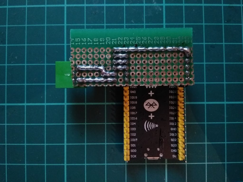
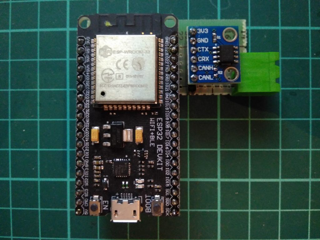
I’ve found that ESP32 has a CAN interface too so I ordered a 3V3 compatible CAN transceiver module SN65HVD230 and assembled a simple prototype board:
Finding the right wires
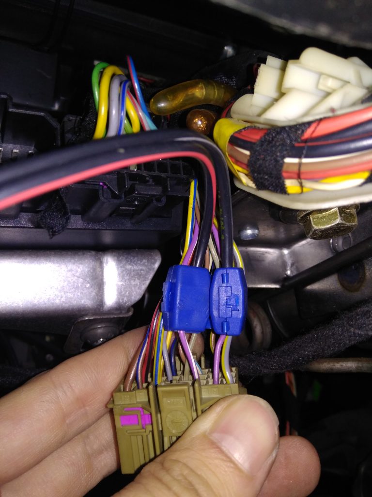
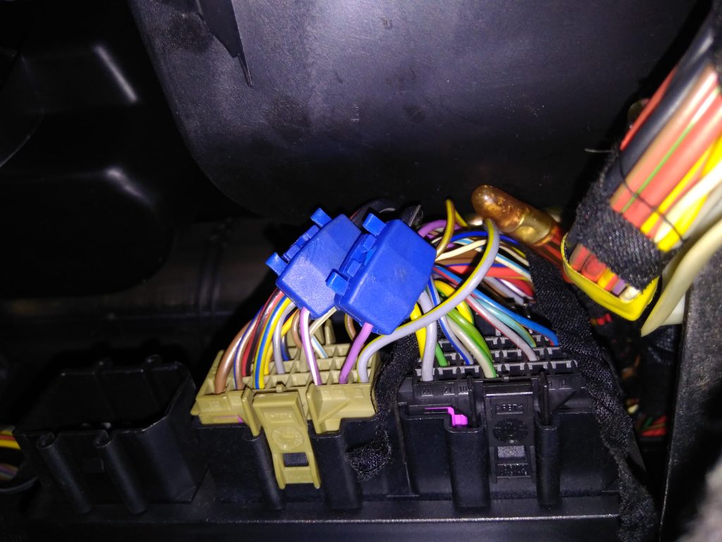
Next challenge was to find and hookup the correct wires in my car. I didn’t want to disassemble doors or some other complicated parts so I Iooked for a pinout of a comfort unit under my steering wheel which is more or less accessible. I was able to find this post which also has a nice picture of the comfort unit so I knew what to search for and which pins (6 and 9) to hookup.
Cable colours were different but after probing with scope the signal was there.
I’ve built an example project for esp32 CAN and went for a first test.
First test
After connecting the module to prepared wires, no packets were received. So I measured the wires again to see the signal.
This didn’t look like a differential pair, moreover not even like 62.5kbps but rather 100kbps. After some more tests I went back to my research.
Proper documentation
After some search I’ve found an another documentation, this time for Volkswagen group’s CAN bus. And this was some interesting reading!
First of all, I found out that 62.5kbps is not used anymore in comfort buses after year 2000 (page 4), it was replaced with 100kbps which was in match with my measurements. Next point was diagnosing errors on the bus. I’ve found an example fault (page 50) which was describing my situation: identical signal on both wires caused by a short between bus wires. This led me to a possible cause: 120 Ohm terminator in my CAN transceiver module. After removing it, the signal returned back to differential:
After this, my module also started to receive packets:
New standard frame from 0x00000151, DLC 4, Data 0x00 0x00 0xF8 0xF8
New standard frame from 0x00000591, DLC 3, Data 0x47 0x00 0x8B
New standard frame from 0x00000371, DLC 1, Data 0xC0
New standard frame from 0x00000601, DLC 1, Data 0x00
New standard frame from 0x00000401, DLC 6, Data 0x02 0x01 0x00 0x00 0x00 0x00
New standard frame from 0x00000353, DLC 8, Data 0x80 0x00 0x00 0x4F 0x00 0x02 0x00 0x00
New standard frame from 0x00000635, DLC 3, Data 0x00 0xFF 0x00
New standard frame from 0x00000351, DLC 8, Data 0x80 0x00 0x00 0x01 0x00 0x7D 0x7D 0x00
New standard frame from 0x00000402, DLC 6, Data 0x03 0x01 0x00 0x00 0x00 0x00
New standard frame from 0x00000551, DLC 1, Data 0x02
New standard frame from 0x00000621, DLC 3, Data 0x00 0x72 0x6D
New standard frame from 0x000005C3, DLC 2, Data 0x00 0x00
New standard frame from 0x000003B5, DLC 5, Data 0x80 0x00 0x00 0x8C 0x04
New standard frame from 0x000002B1, DLC 2, Data 0x05 0x00
New standard frame from 0x00000381, DLC 5, Data 0x00 0x0C 0x00 0x8C 0x04
New standard frame from 0x00000281, DLC 2, Data 0x05 0x00
New standard frame from 0x00000293, DLC 2, Data 0x15 0x01
New standard frame from 0x00000271, DLC 1, Data 0x03
New standard frame from 0x00000151, DLC 4, Data 0x00 0x00 0x48 0x48
New standard frame from 0x00000403, DLC 6, Data 0x08 0x01 0x00 0x00 0x00 0x00
New standard frame from 0x00000353, DLC 8, Data 0x80 0x00 0x00 0x4F 0x00 0x02 0x00 0x00
New standard frame from 0x00000408, DLC 6, Data 0x01 0x01 0x00 0x00 0x00 0x00
New standard frame from 0x00000351, DLC 8, Data 0x80 0x00 0x00 0x01 0x00 0x7D 0x7D 0x00
New standard frame from 0x000005C3, DLC 2, Data 0x00 0x00
New standard frame from 0x00000621, DLC 3, Data 0x00 0x72 0x6D
New standard frame from 0x000003B5, DLC 5, Data 0x80 0x00 0x00 0x8C 0x04
New standard frame from 0x000002B1, DLC 2, Data 0x05 0x00
New standard frame from 0x00000381, DLC 5, Data 0x00 0x0C 0x00 0x8C 0x04
New standard frame from 0x00000281, DLC 2, Data 0x05 0x00
New standard frame from 0x00000293, DLC 2, Data 0x15 0x01
New standard frame from 0x00000271, DLC 1, Data 0x03
New standard frame from 0x00000151, DLC 4, Data 0x00 0x00 0x98 0x98
New standard frame from 0x00000591, DLC 3, Data 0x47 0x00 0x8B
New standard frame from 0x00000371, DLC 1, Data 0xC0
Then I have modified the code to be able to easily extract packets and work with them in python. I captured a few events with notes on what has been done (closing doors, locking, etc.) so I could try to decode the messages.
Sending messages
I wanted to create a PoC smartphone controled central locking. I changed the code to allow sending messages out of my PC with my python script.
$ ./client.py 02811500
UDP target IP: 192.168.4.1
UDP target port: 3333
03b5 8200000c04
0293 0101
0591 47048b
0293 0201
0591 47018b
03b5 8600000c04
02b1 0100
I tried to resend a few of the received messages and some of them really locked doors. The problem was with controlling of all doors. The lock signal worked only for three doors and the trunk. I think, this is because if you lock left front door with a key, the signal is sent to the other doors but in the same doors it is processed internally. So I also captured signals after locking with key in the right front doors and it had a different message ID.
- locking from LF door: 0x0281 8100
- locking from RF door: 0x02b1 8100
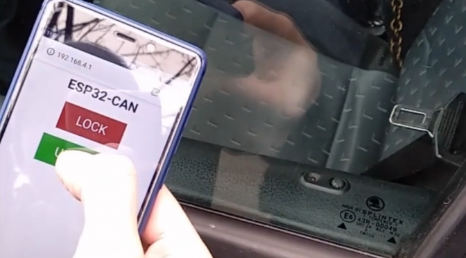
So my solution was to send both of these signals so I changed the code, included a webserver and tested it.
You can see it in action here:
It works so-so but as a PoC it’s enough. My next car will be definitely one with an electromechanical power steering which can be controlled via CAN so I can make some experiments with autonomous driving. As a teaser for this technology you can watch this video:
If you have any questions on comments, feel free to ask.
Bye!


Can you share your esp32 code?
It’s in the the text.
https://github.com/danielkucera/esp32-can
Getting this error:
In file included from C:\Users\xxx\Documents\Arduino\libraries\ESP32-Arduino-CAN-master\src/ESP32CAN.h:4:0,
from C:\Users\xxx\Desktop\ESP32-Arduino-CAN-master\examples\esp32can_basic\esp32can_basic.ino:4:
C:\Users\xxx\Documents\Arduino\libraries\ESP32-Arduino-CAN-master\src/CAN_config.h:32:10: fatal error: freertos/FreeRTOS.h: No such file or directory
#include “freertos/FreeRTOS.h”
^~~~~~~~~~~~~~~~~~~~~
compilation terminated.
exit status 1
Error compiling for board Arduino Uno.
Where can I find freertos? Thanks
Hi Claus, since some time already, I switched to esp-idf TWAI implementation (https://docs.espressif.com/projects/esp-idf/en/latest/esp32c3/api-reference/peripherals/twai.html) and to ESP32-C2 also.
You can see my code at different branch epb (https://github.com/danielkucera/esp32-can/tree/epb)
I am also preparing more posts about emulating EPB, ACC and other powertrain hack.
Hi,
Thanks for your reply. Do you have a simple example of getting the VIN of the car?
I’m stilling trying to learn 🙂
(if you could share using e-mail it would be fantastic)
Hi.
Forgive google translate for my English 😀
Thanks to you I have managed to connect to the CAN. but I can’t send the codes from ESP32 with the example programs.
I have read in my Dacia Doker:
New standard frame from 0x0000055D, DLC 8, Data 0x00 0xFD 0x50 0xC0 0x91 0x00 0x00 0x01
The last data indicates:
0x00 – open car
0x01 – closed car
0x03 – close key button (appears for two seconds)
0x06 – open key button (appears for two seconds)
If I send these codes to the CAN, nothing happens 🙁
Can you help me please, how do you send the codes? 🙂
Can you share your code?
Yes!
It is a modification of the original example, that I have added a quick filter from the terminal and a blacklist of discarded ID’s.
I also write through a terminal command to be able to monitor the changes
Thank you! 🙂
#include
#include
#include
CAN_device_t CAN_cfg; // CAN Config
unsigned long previousMillis = 0; // will store last time a CAN Message was send
const int interval = 1000; // interval at which send CAN Messages (milliseconds)
const int rx_queue_size = 10; // Receive Queue size
String filtros[10] = {“90”, “c6”, “1b0”, “350”, “242”, “29c”, “12e”, “0”, “0”, “0”}; //ignored ID’s
String filtro = “0”;
String data;
String valorstr;
void setup() {
Serial.begin(115200);
Serial.println(“Basic Demo – ESP32-Arduino-CAN”);
CAN_cfg.speed = CAN_SPEED_500KBPS;
CAN_cfg.tx_pin_id = GPIO_NUM_5;
CAN_cfg.rx_pin_id = GPIO_NUM_4;
CAN_cfg.rx_queue = xQueueCreate(rx_queue_size, sizeof(CAN_frame_t));
// Init CAN Module
ESP32Can.CANInit();
}
void loop() {
if (Serial.available()) {
data = Serial.readStringUntil(‘\n’);
if (data == “x”) { //lanzamos la trama desde el terminal
CAN_frame_t tx_frame;
tx_frame.FIR.B.FF = CAN_frame_std;
tx_frame.MsgID = 0x55D;
tx_frame.FIR.B.DLC = 8;
tx_frame.data.u8[0] = 0x00;
tx_frame.data.u8[1] = 0xFD;
tx_frame.data.u8[2] = 0x05;
tx_frame.data.u8[3] = 0xC0;
tx_frame.data.u8[4] = 0x91;
tx_frame.data.u8[5] = 0x00;
tx_frame.data.u8[6] = 0x00;
tx_frame.data.u8[7] = 0x03; //open car??
ESP32Can.CANWriteFrame(&tx_frame);
}
else {
filtro = data;
}
}
CAN_frame_t rx_frame;
unsigned long currentMillis = millis();
// Receive next CAN frame from queue
if (xQueueReceive(CAN_cfg.rx_queue, &rx_frame, 3 * portTICK_PERIOD_MS) == pdTRUE) {
valorstr = String(rx_frame.MsgID, HEX);
if (valorstr == filtro || filtro == “0”) {
if (valorstr != filtros[0] && valorstr != filtros[1] && valorstr != filtros[2] && valorstr != filtros[3] && valorstr != filtros[4] && valorstr != filtros[5] && valorstr != filtros[6] && valorstr != filtros[7] && valorstr != filtros[8] && valorstr != filtros[9]) {
if (rx_frame.FIR.B.FF == CAN_frame_std) {
printf(“std”);
printf(“,”);
}
else {
printf(“extended”);
printf(“,”);
}
if (rx_frame.FIR.B.RTR == CAN_RTR) {
printf(” RTR from ,0x%08X, DLC ,%d\r\n”, rx_frame.MsgID, rx_frame.FIR.B.DLC);
}
else {
printf(“ID,0x%08X, DLC ,%d, Data,”, rx_frame.MsgID, rx_frame.FIR.B.DLC);
for (int i = 0; i < rx_frame.FIR.B.DLC; i++) {
printf("0x%02X", rx_frame.data.u8[i]);
printf(",");
}
printf("\n");
}
}
}
}
}
I looks quite reasonable. Did you check that the code inside `if (data == “x”) { … }` is executed? With some printf e.g.?
yes, I put a feedback from serial port.
I deleted it after checking that it works.
The “matrix” is stopped a few seconds when i send, but no more effect
Maybe the pattern is more complicated than you think and you need to send more messages.
This ID may be the mirror of the locking or the key system, not the door.
I keep playing the Matrix … “There are no unanswered questions, only poorly formulated questions” 🙂
Thks!!! 🙂
Hi,
first of all, thank you for this awesome post. It helped me a lot when I was trying to hack my car 🙂
Just note that in case of comfort unit `1C0 959 799 A` and electric windows only in the front (I know, it suppose to be 21st century) locking and unlocking bit differs. I used Linux based system instead of ESP32, but principle is the same. Hope it helps someone:
“`
# Unlock
cansend can0 281#8500
cansend can0 291#4AAA00
sleep 0.5
cansend can0 291#4AAA00
“`
“`
# Lock
cansend can0 291#8A0001
sleep 0.5
cansend can0 291#8A0001
cansend can0 281#1500
“`
The number before hashtag is arbitrary ID and everything after it is payload. So if leading zero will be added and removed hashtag, you can copy/paste that one.
Hi,
I got the same car and the ODB2 interface is only accessable if the ignition is ON. So I thought the CAN bus will be disabled if the car is “sleeping”.
Is this wrong? Is the bus running all the time? Does your unlock-via-app work even days after locking it (when electricity was clearly at “sleep state”) ?
What car you have?
Octavia 1u5 date 03/2002. (# 8004 / 354)
To clearify; The ODB2-Bluetooth-dongle can only connect if the ignition is ON, that is why i assume the bus in the ODB2 interface is dead then.
Oh, of course. Engine CAN is only on when the engine is on. Comfort CAN is alive all the time.
Okay, I still can’t say if the OBD2 CAN Port is separate to the comfort CAN and to the Engine CAN (OBD2 Interface == Engine CAN?), but the important question of the comfort CAN was answered now, thanks.
-> The comfort CAN is running all the time.
I hope to find the correct wires and can then control the door locks, too. Many thanks for your support and your documentation about it all!
I think I have complete car schematics somewhere. If you want them, contact me using contact form.
Hello. Is it possible to connect to the vehicle via CAN Bus or OBD and send the immobilizer key? Keyless entry of an RFID module and trying to start the engine.
But my car doesn’t work because of immobilizer
danman
23. FEBRUARY 2021 AT 23:07
I think I have complete car schematics somewhere. If you want them, contact me using contact form.
Hi, I am interested in the different cans in car, I am a citizen researcher and hobbiest, I request you to please share the schematics with me, I will also like to know if you can share material on Toyota corolla.
Thanks in advance ..
No, I only have Skoda Octavia I.
Hi , I am playing with esp32 and SN65HVD230 to acts a medium to get data from obd2 port . Not able to connect with can bus . i am trying to connect with bike and car.
can you help me out fit it
Maybe.
Does the comfort canbus stay active even after ignition is off? Will it work even if ignition is off?
It goes to sleep but after sending a few messages the ECUs will wake up.
So basically sending the open command a few times should wake it up? Also is it possible to coonect to obd2 port? Or need to find the comfort can cables directly.
Thanks!
Yes, that is what I do.
No, it’s not on obd2 port, you need to find correct wires.