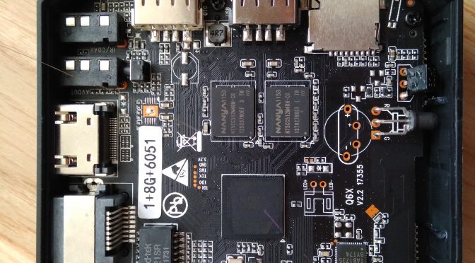
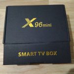
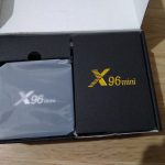
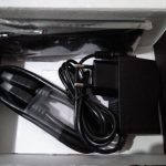
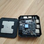
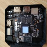
So I bought a media player again. It’s Vontar X96 mini with 1GB RAM and 8GB eMMC and according to rule “Don’t turn it on, take it apart!” it’s exactly what I did:
After assembling and turning it on, Android 7 popped up but this was not my target OS. I wanted to use LibreELEC so I followed installation howto: downloaded and burned latest image to SD card, replaced dtb file with gxl_p212_1g.dtb, and run reboot update from Android terminal.
Box rebooted into working LibreELEC, nice! Now I wanted to burn it into internal eMMC so I run installtointernal despite a big red warning on howto page and warning in the script itself, rebooted and… I got sad. The LED was blinking red-blue and the box stopped booting. I tried all voodoo recovery instructions (holding reset button, powering from both usb and adapter, with HDMI, without it…) to boot into upload mode where the box would be detected by a PC and I would use USB Burning Tool but nothing helped. I also wrote to the seller to get help, they’ve sent me USB Burning Tool, factory image and Upgrade instruction which was nice but it didn’t work either.
So I hooked up serial interface to see what’s going on inside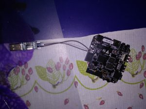 and the result was following:
GXL:BL1:9ac50e:a1974b;FEAT:ADFC318C;POC:3;RCY:0;EMMC:0;READ:0;0.0;CHK:0;
TE: 100781

BL2 Built : 20:32:17, Sep 8 2017.
gxl g6296b83 - xiaobo.gu@droid12

set vcck to 1120 mv
set vddee to 1070 mv
Board ID = 2
CPU clk: 1200MHz
DQS-corr enabled
DDR scramble enabled
DDR3 chl: Rank0 16bit @ 792MHz
Rank0: 1024MB(auto)-2T-11
DataBus test pass!
AddrBus test pass!
-s
Load fip header from eMMC, src: 0x0000c200, des: 0x01400000, size: 0x00004000
New fip structure!
Load bl30 from eMMC, src: 0x00010200, des: 0x01100000, size: 0x0000d600
Load bl31 from eMMC, src: 0x00020200, des: 0x05100000, size: 0x0002c600
Load bl33 from eMMC, src: 0x00050200, des: 0x01000000, size: 0x00065e00
NOTICE: BL3-1: v1.0(release):a625749
NOTICE: BL3-1: Built : 11:25:15, Aug 25 2017
[BL31]: GXL CPU setup!
NOTICE: BL31: BL33 decompress pass
mpu_config_enable:ok
[Image: gxl_v1.1.3243-377db0f 2017-09-07 11:28:58 qiufang.dai@droid07]
OPS=0xa2
0 a4 b0 46 ef c9 98 14 5e dc ac 58 [0.326773 Inits done]
secure task start!
high task start!
low task start!
ERROR: Error initializing runtime service opteed_fast


U-Boot 2015.01-g2d1a155-dirty (Oct 08 2017 - 12:02:50)

DRAM: 1 GiB
Relocation Offset is: 36eb3000
register usb cfg[0][1] = 0000000037f5a960
[CANVAS]canvas init
boot_device_flag : 1
Nand PHY Ver:1.01.001.0006 (c) 2013 Amlogic Inc.
init bus_cycle=6, bus_timing=7, system=5.0ns
reset failed
get_chip_type and ret:fffffffe
get_chip_type and ret:fffffffe
chip detect failed and ret:fffffffe
nandphy_init failed and ret=0xfffffff1
MMC: aml_priv->desc_buf = 0x0000000033eb36b0
aml_priv->desc_buf = 0x0000000033eb59d0
SDIO Port B: 0, SDIO Port C: 1
emmc/sd response timeout, cmd8, status=0x1ff2800
emmc/sd response timeout, cmd55, status=0x1ff2800
init_part() 293: PART_TYPE_AML
[mmc_init] mmc init success
dtb magic edfe0dd0
 Amlogic multi-dtb tool
 Single dtb detected
start dts,buffer=0000000033eb8200,dt_addr=0000000033eb8200
 Amlogic multi-dtb tool
 Single dtb detected
parts: 11
00: logo 0000000002000000 1
01: recovery 0000000002000000 1
02: rsv 0000000000800000 1
03: tee 0000000000800000 1
04: crypt 0000000002000000 1
05: misc 0000000002000000 1
06: boot 0000000002000000 1
07: system 0000000080000000 1
08: cache 0000000020000000 2
09: data ffffffffffffffff 4
"Synchronous Abort" handler, esr 0x96000210
ELR: 37ec0b44
LR: 37ec0afc
x0 : 0000000033f38210 x1 : 000000000000000c
x2 : 0000000037f443f9 x3 : 0000000000000004
x4 : 0000000000000000 x5 : 0000000033f383a0
x6 : 0000000033ec13b0 x7 : 0000000000000020
x8 : 0000000000000034 x9 : 0000000000000000
x10: 000000000000000f x11: 0000000037f38d00
x12: 0000000000000000 x13: 0000000000000000
x14: 0000000000000000 x15: 0000000000000000
x16: 0000000000000000 x17: 0000000000000000
x18: 0000000033ea2e28 x19: 000000000000000a
x20: 0000000000000000 x21: 0000000033eb8200
x22: 0000000000000000 x23: 0000000033ebe6bc
x24: 0000000037f72000 x25: 0000000000000000
x26: 0000000000006468 x27: 0000000000000000
x28: 000000000000000a x29: 0000000033e92b70

Resetting CPU ...

resetting ...
GXL:BL1:9ac50e:a1974b;FEAT:ADFC318C;POC:3;RCY:0;EMMC:0;READ:0;0.0;CHK:0;
TE: 100780

BL2 Built : 20:32:17, Sep 8 2017.
gxl g6296b83 - xiaobo.gu@droid12

set vcck to 1120 mv
set vddee to 1070 mv
Board ID = 2
CPU clk: 1200MHz
DQS-corr enabled
DDR scramble enabled
DDR3 chl: Rank0 16bit @ 792MHz
Rank0: 1024MB(auto)-2T-11
DataBus test pass!
AddrBus test pass!
-s
Load fip header from eMMC, src: 0x0000c200, des: 0x01400000, size: 0x00004000
New fip structure!
Load bl30 from eMMC, src: 0x00010200, des: 0x01100000, size: 0x0000d600
Load bl31 from eMMC, src: 0x00020200, des: 0x05100000, size: 0x0002c600
Load bl33 from eMMC, src: 0x00050200, des: 0x01000000, size: 0x00065e00
NOTICE: BL3-1: v1.0(release):a625749
NOTICE: BL3-1: Built : 11:25:15, Aug 25 2017
[BL31]: GXL CPU setup!
NOTICE: BL31: BL33 decompress pass
mpu_config_enable:ok
[Image: gxl_v1.1.3243-377db0f 2017-09-07 11:28:58 qiufang.dai@droid07]
OPS=0xa2
0 a4 b0 46 ef c9 98 14 5e dc ac 58 [0.326738 Inits done]
secure task start!
high task start!
low task start!
ERROR: Error initializing runtime service opteed_fast


U-Boot 2015.01-g2d1a155-dirty (Oct 08 2017 - 12:02:50)

DRAM: 1 GiB
Relocation Offset is: 36eb3000
register usb cfg[0][1] = 0000000037f5a960
[CANVAS]canvas init
boot_device_flag : 1
Nand PHY Ver:1.01.001.0006 (c) 2013 Amlogic Inc.
init bus_cycle=6, bus_timing=7, system=5.0ns
reset failed
get_chip_type and ret:fffffffe
get_chip_type and ret:fffffffe
chip detect failed and ret:fffffffe
nandphy_init failed and ret=0xfffffff1
MMC: aml_priv->desc_buf = 0x0000000033eb36b0
aml_priv->desc_buf = 0x0000000033eb59d0
SDIO Port B: 0, SDIO Port C: 1
emmc/sd response timeout, cmd8, status=0x1ff2800
emmc/sd response timeout, cmd55, status=0x1ff2800
init_part() 293: PART_TYPE_AML
[mmc_init] mmc init success
dtb magic edfe0dd0
 Amlogic multi-dtb tool
 Single dtb detected
start dts,buffer=0000000033eb8200,dt_addr=0000000033eb8200
 Amlogic multi-dtb tool
 Single dtb detected
parts: 11
00: logo 0000000002000000 1
01: recovery 0000000002000000 1
02: rsv 0000000000800000 1
03: tee 0000000000800000 1
04: crypt 0000000002000000 1
05: misc 0000000002000000 1
06: boot 0000000002000000 1
07: system 0000000080000000 1
08: cache 0000000020000000 2
09: data ffffffffffffffff 4
"Synchronous Abort" handler, esr 0x96000210
ELR: 37ec0b44
LR: 37ec0afc
x0 : 0000000033f38210 x1 : 000000000000000c
x2 : 0000000037f443f9 x3 : 0000000000000004
x4 : 0000000000000000 x5 : 0000000033f383a0
x6 : 0000000033ec13b0 x7 : 0000000000000020
x8 : 0000000000000034 x9 : 0000000000000000
x10: 000000000000000f x11: 0000000037f38d00
x12: 0000000000000000 x13: 0000000000000000
x14: 0000000000000000 x15: 0000000000000000
x16: 0000000000000000 x17: 0000000000000000
x18: 0000000033ea2e28 x19: 000000000000000a
x20: 0000000000000000 x21: 0000000033eb8200
x22: 0000000000000000 x23: 0000000033ebe6bc
x24: 0000000037f72000 x25: 0000000000000000
x26: 0000000000006468 x27: 0000000000000000
x28: 000000000000000a x29: 0000000033e92b70

Resetting CPU ...

resetting ...
The box was in a boot loop without accepting any input or keystrokes. Some guides suggest to short out some pins on flash chip but my eMMC has BGA package so this was not possible. I randomly shorted out some resistors and capacitors nearby the eMMC but without luck. I was afraid I’ll need to use JTAG which seemed quite hard to solder and there were no howtos for using this method. Then I took some time to rethink this.
The point of shorting out pins is to avoid detecting the eMMC and to force the main chip boot into upload mode. So to avoid detecting it, it should be enough to break the communication by grounding some of the DATA, CLK or CMD lanes. So again I took ampermeter (to see if I’m not grounding power lane), attached one probe to GND and with the other one I was probing pins around the eMMC chip. After few tries, the status LED stayed blue and the board got detected, bingo!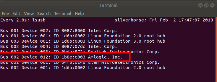
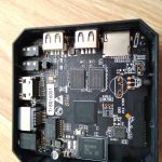
For those with the same board, it was this pin:
You can find GND on all connector shields (HDMI, USB).
Now it was just a piece of cake, I connected it to Windows machine, grounded pin again and used the upload utility:
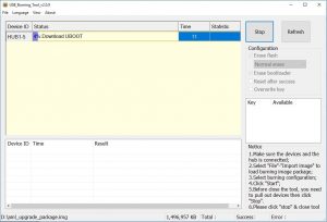
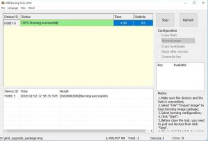 Of course I tried to run and install LibreELEC to eMMC again but this time it worked and I wasn’t able to simulate the boot loop again, even with uploading garbage to /dev/dtb.
Hope this guide will help someone, if you have some questions or ideas please leave a comment.
Bye!
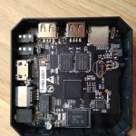
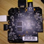
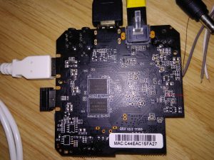
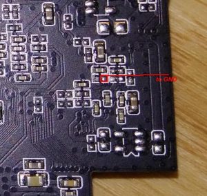
Hello Danmman
I have the same probem.
Can you show which pin must I shorten with GND on picture please ??
Hi Giorgi, try to zoom in pictures in article. There is a red line marking the pin.
danman y have the same motherboard,bot there y have another thing one rezistor y think my box with usb burning tool,stock on 7% with error and with Sd card show logo boot a Little and stock the same with a Little green line….what y have to do?Please help me!!thank You!!!
My friend was able to solve this mistake I have?
Hello,
I Already short to ground like your picture, but my light still got red and when i use USB Burning Tool I got Error on 2% Proced..
can you help me to explain more detail about all process because i’m not to much understand.
Thx Danman
If your box is detected (it must be when you are able to get to 2%) then it has to be some different problem. Maybe your eMMC is damaged, I don’t know.
I change my image with”x96mini_20171202″ and the process now error at 7% ([0x32030201]Uboot/Get result/DiskInitial error)
Sorry I mean now when i flash my x96 mini always got error at 7%
hello friend you have managed to find a solution to your problem with your box
Same problem, but nothing happens when I short it.
I have still the some on MXIII-G 🙁
Hello…
My Problem Solved by this trick…thx
i think my emmc was problem so after flashing done the problem now is boot loop
plz i have same error code in 2%…how to solve it?
Dear Danman,
I have same problem, my X96 mini LED is blue, X96 recognized by USB burning tool, but stuck at 7%:formatting. I could not load with SD card, which prepared with *.img file, HDMI on TV does not recognize Box, even LED is blue.
Do you have any suggestion??
Thanks and regards,
Thank you, a few month ago I tried everything but couldn’t get the box recognized by my PC.
With this guide I was able to reinstall the stock rom again. 👍🤗
I’m glad it helped 🙂
Hello,
I Already short to ground like your picture, but my light still got red and when i use USB Burning Tool it still not detected my device can u help me out how to make it detected?
Did you try connect serial port to see what it does?
Hello Danman first of all thanks for the information that you provided, I have a very strange issue with my X96 mini, It does not boot and LED remains red (should turn blue). Finally I found a way how to boot it up but I did not solve the problem, I found a repetitive way to boot it up and its very strange. while booting I am touching the base of the board in the area underneath the SD card port. When I simply touch it with my finger the LED turns blue and the box boots up. At first I thought it was a coincidence but I did it several times. I don’t think its a case of a dry joint but I am suspecting its a grounding issue. What do you think about it? Strange isn’t it? I am thinking of buying a more powerful power supply.
By the way after few minutes after boot up it will freeze and would need to remove the supply and do the same procedure in order to reboot.
Hello, with touch I think you cannot improve grounding, I would guess it’s a bad solder joint. Maybe ask in some electronics repair shop in your location.
Yes i think u might be right. In fact after posting the message I tried to solder some solder points. It took muck longer to freeze but still it did the same thing. I will try to see what I can do to solder al the points possible because most of them are very very tiny,
Thanks you sooooo much. My box is alive
Plz tellme hows your device is alive… I jave x96 mini s905w, q6x v2.2
It is brick now
Plz email me at this
mananb80@gmail.com
I couldn’t have installed stock firmware back again without your post. Thank you.
I have a box x96 s905w and when I want to add the firmware I get this error *[0x32030201]Uboot/Get result/DiskInitial error, can give me some solution to my problem
Should I just touch the pin with the screwdriver? With what and how should I touch the pin and where is gnd? Plz explain thank you
Take a wire. With one end, touch the HDMI connector shield for example and with the other end touch the marked pin.
Thanks a bunch, i know its been 2 years since your post, previously i was thinking that GND is negative (-) in power source, until i see this reply
Hi I try the method and no lucky, I ground to case of HDMI and only red light , and USB flash tool not detected. Here a photo any can help ? Thx
https://ibb.co/hbwu1p
Hello, so far it have worked for many people. Does your computer detect the device? Do you have a correct (crossover) cable?
Hello thx for reply me, I’m using a USB cable of a external CD-ROM, this one have double power USB. Here a photo ,
https://ibb.co/jRRTYe
The program USB tool don’t detect nothing , I only get red light when I power x96.
Ah, that’s the problem, you need to use a proper USB A male to USB A male cable.
Where is GND?
Nothing happens when i touch that red marked resistor.
Hi, excactly was the cable, i homemade one using two males and cut, and worked!
thx for this nice tip!!
On the google drive link, there is no factory image.
Only USB Burning Tool, & Upgrade instruction.
Can you kindly tell us where to find the factory image.
Thank you
Hello, you can find that file here:
https://cloud.danman.eu/index.php/s/PKLRW2B6GzrSfEs
The file’s no longer available. Could you reupload it please?
It is there…
I’m getting a file not found error whenever I try to download from there though. :/
You were right, here it is again:
https://cloud.danman.eu/index.php/s/PKLRW2B6GzrSfEs
Hi there, there is no image in the link provided
Nvm i got it thanx, i just have an issue, i am connected via the hub, but i get an error at 9% complaining about UBOOT partitions that fail. I tried so many different images and the same.
Many thanks for the file, but I’m not able to get a blue light . Solid red or flashing red (when I short to the gnd)
The market spot is not working. The one on the left disconnects the board from the pc.
Any other spot that I can check? I have the same board.
Thanks
Mine flashed blue in another spot which is right under the led indicator where you’ll find two very small black chip(don’t know what they are called).grounding one of them might turn the indicator blue.just poke around in that place and it may turn blue.but I was still unable to flash mine and the error still occurred.I hope it works for you.my screw driver couldn’t ground so I used a tweezer.
You are just shorting the LED and the blue light comes up. That won’t trigger anything unfortunately.
Thank you!
It also revived my x96mini after trying to use a modified 8.0-rom(what just led to a poor red/blue lightshow). Cool thing to get it work again just with a short piece of wire in minutes..
More info please.
Use burn card maker for repair it
Hi!
i have a T95U Pro tv box and it stays in a blue light and dont boot at all.
USB Burning tool recognize it but whe i try to flash it with the stock ROM it stucks to 7% formatting with the following error “0x32030201]Uboot/Get result/DiskInitial error”
Any advise to revive my device?
Thank you
i have the 2gb series of x96 mini is the same location for grounding short pin??
Also, does anyone have a working ROM for the “Q6X v2.2 17355” as pictured in this post?
GND ?? To USB Port GND.
I have a request – could anyone give the value of this resistor to which the wire is soldered? Because I inadvertently damaged it during soldering on the main board
Thanks for help. I cant understand correctly. I cant understand English very well. Google translate cant help me. Sorry.
“So again I took ampermeter (to see if I’m not grounding power lane), attached one probe to GND and with the other one I was probing pins around the eMMC chip. After few tries, the status LED stayed blue and the board got detected, bingo!”
x96 mini plug in electric: yes
One probe attached GND: yes
But other one? Where is eMMC chip and which probe? I dont want to a mistake. Can you upload detailed photo please?
Thank you so much in advance.
Find it. Detect PC. Thanks. 🙂
have solved the issue man, plz send the details.
dear Sir, my x96mini got stuck after i received an officail OTA update, it got stuck at 97%. after serveral attempts. i tried to recover it via sd-card by pressing reset button via AV hole, but unfortunately i used metal pin, when i saw android logo started moving progress-bar, i think pin just shorted when i tried to pull the pin out. from then onwards it shows only red led (static).
i have the exact replica board and i identified the pin, but i am not getting how to ground the pin.
plz help me to sort it out.
HI everyone! I have two X96 mini tv boxes with different stocks.
One of them opens this program without any problem. Link for program is here:
!!!POTENTIALLY RISKY CONTENT!!!: https://cloud.mail.ru/stock/7uRgfhaTfR9ebxC4Nj58cd9X
Another tv box doesn’t open this program. Opens then closes in a few seconds. Can u help me please. what is the prolem?
I need this program!
Thank you for your attention!
Hello .
please i want to know how to install wifi antenna. want to tell me where i can plug the queues so.
thank you.
I have same box but with 2G ram and 16G of emmc. I hooked serial console on fresh opened box but I cannot see any output. Anyone with same stuff? Boar is Q6X v2.3 Thanks
Please use video about this. i don’t get it.
My box detected PC but still have error
[0x10103005]Romcode/Initialize DDR/Download buffer/Read item data failed
Same issue,
suggest just install CoreElec or LibreElec and do > installtointernal
maybe best to clear internal flash prior to work first time.
1/8GB modelonly real downside is no wakeup with remote {dont have original}
Have you find this solution… I have the same issue…if you find then plz email me the way
mananb80@gmail.com
Work fine thanks you
Didnt work me n many others. Can u plz share how u did it. How u short the wire might how we r shortening the wire isnt the right way. Thanks
If you don’t know how to short one pin to ground perhaps you shouldn’t be doing it at all.
Hi,
Do you still have the firmware? its not in the google drive.
Link updated.
Hi Danman, Q?
Do I have to connect power cord when shorting that pin to ground or only USB connected to pc?
For me powering from USB was enough.
romcode/initialize ddr/download buffer/read item data failed x96mini esta dando esse erro
Have you find this solution??
excelente informacion, pude revivir mi x96mini
excellent information, I was able to revive my x96mini
For those who stuck at 7%, you have to flash with an original x96 mini original firmware.
By the way, great job DANMAN. Thanks to you, i was able to make my x96 mini work again.
Thanks
How you recover your device plz tell me at my email address
mananb80@gmail.com
Hey maybe you can help me too!
I have T95z plus and I did a factory reset now it just loads and gets stuck at T95Z plus screen every time. I can hold down boot button and get into recovery mode but I can’t get anything in there to help. Any ideas?
Sorry I am noob I found the pin but where is the ground pin ?
It worked for me.
For ground pin I use the metal part around the USB male connector.
I used a multimeter to do this but simple electric cable should work.
I also had the 2% problem, so 2 things are important:
1 – take care of you cable quality and don’t use any extension
2 – use the usb ports connected to the motherboard
It doesn’t like interference, overall quality of theses cards is not the best (I had the same problems when flashing Wiko phones)
Good luck 🙂
Thank you so much for this article. I had same problem with different board, i started shorting random pins around eMMC and bingo, my device got detected by windows. The rest was easy 🙂
Just wanted to say THANK YOU for having taken the time to expose what you did!
And kudos for your debugging technique!
I had the same problem and debricked my X96mini with your magical short circuit.
Thanks!
Michel
Sir plz kindly tell me how you did recover your device… Kindly contact at my email address
mananb80@gmail.com
good night I am new to this and I have several attempts with different roms of the x96 mini of 2gb and 16gb. you could support me with some video tutorial of how you did the procedure of the short since also in red light only the pc detects it but I get error at 2% 0x10105004
Have you find this solution??
My x96 mini keeps on disconnecting again and again. windows 10 detects it without pins being short but disconnects immediately and the cycle continues. short different pins but light is still red. no change, not deducted by Usb tool.
Hi, so I have found myself in the above situation while attempting to update my x96 mini from 7.1.2 to 9.
The LED on my device is blinking red blue red blue and wont come on… I have tried several methods given online but none has worked, so this method will be my last option.
Does this method work on the Q6x v2.3 board?
The principle should be the same, yes.
Thanks so so much! I can confirm that it works! My android box is up and running again. Thank you
Hi,
did you install librelec the second time again with the script and now it worked, or did you flash it with the recovery tool (somehow) directly?
Thanks!
Cheers
4920441
Hallo,
my Vontar x96mini has bricked,
did you have the orginal standard Android 7.12 Image of this Box
i cant find it.
PID